Isuzu KB P190. Manual — part 1435

9A1-58 RESTRAINT CONTROL SYSTEM
DTC Will Clear When
The “Driver Pretensioner Low " voltage comes to
specified voltage.
DTC Chart Test Description
Number(s) below refer to circled number(s) on the
diagnostic chart.
2. This test determines whether the SRS control unit is
malfunctioning.
3. This test isolates the malfunction to one side of the
driver pretensioner assembly yellow connector at the
base of the driver seat.
4. This test determines whether the malfunction is in
“Driver Pretensioner High” circuit.
5. This test determines whether the malfunction is in
“Driver Pretensioner Low” circuit.
Diagnostic Aids
An intermittent condition is likely to be caused by a short
to ground in the driver pretensioner assembly circuit.
Inspect circuits “Driver Pretensioner High” and “Driver
Pretensioner Low” carefully for cutting or chafing. If the
wiring pigtail of the driver pretensioner assembly is
damaged, the component must be replaced. A careful
inspection of “Driver Pretensioner High” and “Driver
Pretensioner Low”, including the driver pretensioner
assembly pigtail is essential to ensure that the
replacement SRS control unit will not be damaged.
DTC B0045 (Flash Code 45) Driver Pretensioner Squib Circuit Short to GND
Step Action
Yes
No
1
Was the “SRS Diagnostic System Check” performed?
Go to Step 2
Go to the “SRS
Diagnostic System
Check”
2
1. When measurements are requested in this chart use a 5-
8840-0366-0 DMM with a correct terminal adapter from 5-
8840-2835-0.
2. Ignition switch is at “LOCK”.
3. Ignition switch is “ON”.
4. Check the driver pretensioner air bag squib circuit for short to
ground.
Was a problem found?
Go to Step 3
3
1. Ignition switch is at “LOCK”.
2. Disconnect driver pretensioner assembly yellow connector at
the base of the driver seat.
3. Leave driver air bag assembly connected.
4. Connect SRS driver / driver load tool 5-8840-2421-0 and
appropriate adapter to driver air bag assembly harness
connector.
5. Ignition switch is at “ON”.
Is DTC B0045 current?
Go to Step 4
Ignition switch is at
“LOCK”.
Replace driver
pretensioner
assembly .
Go to Step 6
4
1. Ignition switch is at “LOCK”.
2. Disconnect the SRS driver /driver load tool.
3. Measure the resistance on the SRS control unit harness
connector as follow.
From terminals "8" to "3" and "15" (ground) (with the
passenger air bag)
From terminals "8" to "3", "12" and "15" (ground) (without
the passenger air bag)
Does 5-8840-0366-0 display “OL” (Infinite)?
Go to Step 5
Replace SRS
Harness.
Go to Step 6
RESTRAINT CONTROL SYSTEM 9A1-59
Step Action
Yes
No
5
Measure the resistance on the SRS control unit harness
connector as follow.
From terminals "7" to "3" and "15" (ground) (with the
passenger air bag)
From terminals "7" to "3", "12" and "15" (ground) (without
the passenger air bag)
Does 5-8840-0366-0 display “OL” (Infinite)?
Go to Chart A
Replace SRS
Harness.
Go to Step 6
6
1. Reconnect all the components and ensure all components
are properly mounted.
2. Clear diagnostic trouble codes.
Is this step finished?
Go to the “SRS
Diagnostic system
Check”
―
9A1-60 RESTRAINT CONTROL SYSTEM
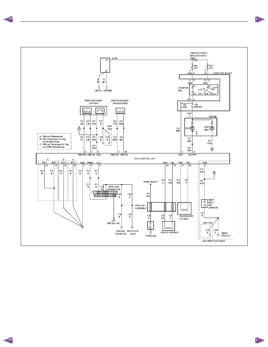
DTC B0046 (Flash Code 46) Driver Pretensioner Squib Circuit Short to Battery
Voltage
RTW79ALF000301
Circuit Description
When the ignition switch is turned “ON”, the SRS
control unit will perform tests to diagnose critical
malfunctions within itself. Upon passing these tests,
“Ignition 1”, and pretensioner loop voltages are
measured to ensure they are within their respective
normal voltage ranges.
The SRS control unit monitors the voltages at “Driver
Pretensioner Low” terminal “7” and “Passenger
Pretensioner Low” terminal “10” to detect short to
ground/+B in the pretensioner assembly circuits.
DTC Will Set When
“Ignition 1" is in the normal operating voltage range.
The voltage at “Driver Pretensioner Low " is above a
specified value,
DTC B0046 will set.
Action Taken
SRS control unit turns “ON” the “SRS” warning lamp
and sets a diagnostic trouble code.

RESTRAINT CONTROL SYSTEM 9A1-61
DTC Will Clear When
The “Driver Pretensioner Low " voltage comes to
specified voltage.
DTC Chart Test Description
Number(s) below refer to circled number(s) on the
diagnostic chart.
2. This test determines whether the SRS control unit is
malfunctioning.
3. This test isolates the malfunction to one side of the
driver pretensioner assembly yellow connector at the
base of the driver seat.
4. This test determines whether the malfunction is in
“Driver Pretensioner High” circuit.
5. This test determines whether the malfunction is in
“Driver Pretensioner Low” circuit.
Diagnostic Aids
An intermittent condition is likely to be caused by a short
to +B in the driver pretensioner assembly circuit.
Inspect circuits “Driver Pretensioner High” and “Driver
Pretensioner Low” carefully for cutting or chafing. If the
wiring pigtail of the driver pretensioner assembly is
damaged, the component must be replaced. A careful
inspection of “Driver Pretensioner High” and “Driver
Pretensioner Low”, including the driver pretensioner
assembly pgtail is essential to ensure that the
replacement SRS control unit will not be damaged.
DTC B0046 (Flash Code 46) Driver Pretensioner Squib Circuit Short to Battery Voltage
Step Action
Yes
No
1
Was the “SRS Diagnostic System Check” performed?
Go to Step 2
Go to the “SRS
Diagnostic System
Check”
2
1. When measurements are requested in this chart use a 5-
8840-0366-0 DMM with a correct terminal adapter from 5-
8840-2835-0.
2. Ignition switch is at “LOCK”.
3. Ignition switch is “ON”.
4. Check the driver air bag squib circuit for a short to voltage.
Was a problem found?
Go to Step 3
3
1. Ignition switch is at “LOCK”.
2. Disconnect driver pretensioner assembly yellow connector at
the base of the driver seat.
3. Leave driver air bag assembly connected.
4. Connect SRS driver / passenger load tool 5-8840-2421-0 and
appropriate adapter to driver air bag assembly harness
connector.
5. Ignition switch is at “ON”.
Is DTC B0046 current?
Go to Step 4
Ignition switch is at
“LOCK.”
Replace driver
pretensioner
assembly .
Go to Step 6
4
Measure the resistance on the SRS control unit harness
connector from terminal “8” to terminal “1” (ignition).
Does 5-8840-0366-0 display “OL” (Infinite)?
Go to Step 5
Replace SRS
Harness.
Go to Step 6
5
Measure the resistance on the SRS control unit harness
connector from terminal “7” to terminal “1” (ignition).
Does 5-8840-0366-0 display “OL” (Infinite)?
Go to Chart A
Replace SRS
Harness.
Go to Step 6
6
1. Reconnect all the components and ensure all components
are properly mounted.
2. Clear diagnostic trouble codes.
Is this step finished?
Go to the “SRS
Diagnostic system
Check”
―
Нет комментариевНе стесняйтесь поделиться с нами вашим ценным мнением.
Текст