Isuzu KB P190. Manual — part 1436

9A1-62 RESTRAINT CONTROL SYSTEM
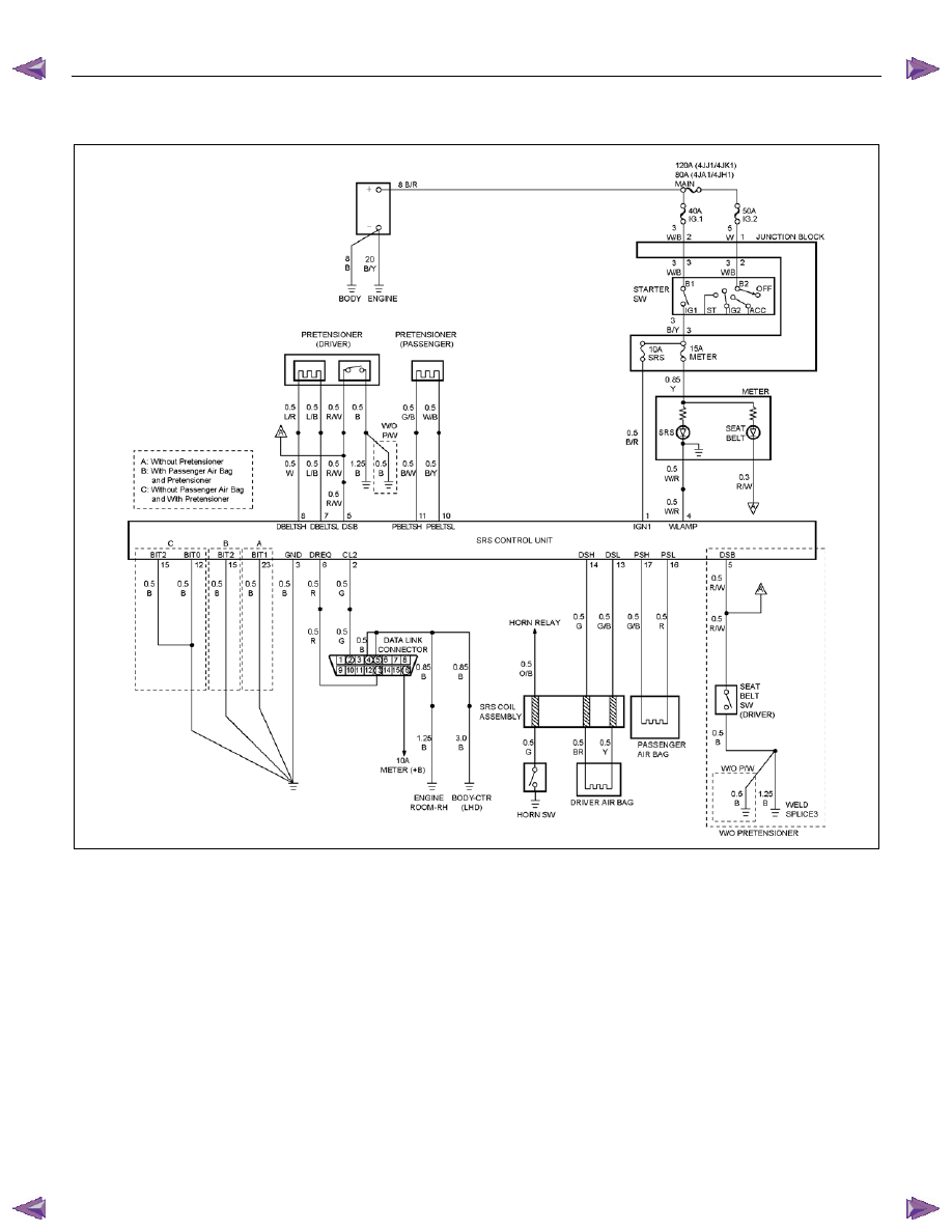
DTC B0051 (Flash Code 51) Air Bag Squib Circuit Activated (Crash)
RTW79ALF000301
Circuit Description
The SRS control unit contains a sensor which converts
vehicle velocity changes to an electrical signal. The
electrical signal generated is processed by the SRS
control unit and then compared to a value stored in
memory. When the generated signal exceeds the
stored value, the SRS control unit will cause current to
flow through the air bag assembly deploying the air
bags and causing DTC B0051 to set.
DTC Will Set When
The SRS control unit detects a frontal crash, up to 30
degrees off the centerline of the vehicle, of sufficient
force to warrant deployment of the air bags.
Action Taken
SRS control unit turns “ON” the “SRS” warning lamp
and records “Crash Data”, and sets a diagnostic trouble
code.
DTC Will Clear When
The SRS control unit is replaced.
DTC Chart Test Description
Number(s) below refer to step number(s) on the
diagnostic chart:
2. If the air bag assembly(s) has not deployed, DTC
B0051 may have been falsely set.
3. If DTC B0051 has set with no signs of frontal impact,
the diagnostic trouble code has been falsely set.

RESTRAINT CONTROL SYSTEM 9A1-63
DTC B0051 (Flash Code 51) Air Bag Squib Circuit Activated (Crash)
WARNING: DURING SERVICE PROCEDURES. BE VERY CAREFUL WHEN HANDLING A SRS CONROL UNIT.
NEVER STRIKE OR JAR THE SRS CONTROL UNIT. NEVER POWER UP THE SRS WHEN THE SRS CONTROL
UNIT IS NOT RIGIDLY ATTACHED TO THE VEHICLE. ALL SRS CONTROL UNIT AND MOUNTING BRACKET
FASTENERS MUST BE CAREFULLY TORQUED AND THE ARROW MUST BE POINTING TOWARD THE FRONT
OF THE VEHICLE TO ENSURE PROPER OPERATION OF THE SRS. THE SRS CONTROL UNIT COULD BE
ACTIVATED AND CAUSE DEPLOYMENT RESULTING IN PERSONAL INJURY.
Step Action
Yes
No
1
Was the “SRS Diagnostic System Check” performed?
Go to Step 2.
Go to the “SRS
Diagnostic System
Check”
2
Ignition switch is at “LOCK”.
Have air bag assemblies been deployed?
Replace
components and
perform
inspections as
directed in “repairs
and inspections
required after an
accident” in this
section.
clear diagnostic
trouble codes.
Repeat “SRS
Diagnostic System
Check”
Go to Step 3
3
Inspect the front of the vehicle and undercarriage for signs of
impact.
Were signs of impact found?
Replace
components and
perform
inspections as
directed in
“Repairs and
Inspections
Required After An
Accident” in this
section.
Clear diagnostic
trouble codes.
Repeat “SRS
Diagnostic System
Check”
Ignition switch
“LOCK”.
Replace SRS
control unit.
Reconnect all SRS
system
components,
ensure all
components are
properly mounted.
Repeat “SRS
Diagnostic System
Check”
9A1-64 RESTRAINT CONTROL SYSTEM
DTC B0052 (Flash Code 52) Pretensioner Squib Circuit Activated (Crushed)
RTW79ALF000301
Circuit Description
The SDM contains a sensing device which converts
vehicle velocity changes to an electrical signal. The
electrical signal generated is processed by the SDM
and then compared to a value stored in memory. When
the generated signal exceeds the stored value, the
SDM will cause current to flow through the pretensioner
seat belt deploying the pretensioner seat belt and
causing DTC B0052 to set.
DTC Will Set When
The SRS control unit detects a frontal crash, up to 30
degrees off the centerline of the vehicle, of sufficient
force to warrant deployment of the pretensioner seat
belt.
Action Taken
SRS control unit turns “ON” the “SRS” warning lamp
and records “Crash Data”, and sets a diagnostic trouble
code.
DTC Will Clear When
The SRS control unit is replaced.
DTC Chart Test Description
Number(s) below refer to step number(s) on the
diagnostic chart:
2. If the pretensioner seat belt assemblies have not
deployed, DTC B0052 may have been falsely set.
3. If DTC B0052 has set with no signs of frontal impact,
the diagnostic trouble code has been falsely set.

RESTRAINT CONTROL SYSTEM 9A1-65
DTC B0052 (Flash Code 52) Pretensioner Squib Circuit Activated (Crash)
WARNING: DURING SERVICE PROCEDURES. BE VERY CAREFUL WHEN HANDLING A SRS CONROL UNIT.
NEVER STRIKE OR JAR THE SRS CONTROL UNIT. NEVER POWER UP THE SRS WHEN THE SRS CONTROL
UNIT IS NOT RIGIDLY ATTACHED TO THE VEHICLE. ALL SRS CONTROL UNIT AND MOUNTING BRACKET
FASTENERS MUST BE CAREFULLY TORQUED AND THE ARROW MUST BE POINTING TOWARD THE FRONT
OF THE VEHICLE TO ENSURE PROPER OPERATION OF THE SRS. THE SRS CONTROL UNIT COULD BE
ACTIVATED AND CAUSE DEPLOYMENT AND RESULTING IN PERSONAL INJURY.
Step Action
Yes
No
1
Was the “SRS Diagnostic System Check” performed?
Go to Step 2.
Go to the “SRS
Diagnostic System
Check”
2
Ignition switch “LOCK”.
Have the pretensioner seat belt assemblies been deployed?
Replace
components and
perform
inspections as
directed in
“repairs and
inspections
required after an
accident” in this
section.
clear diagnostic
trouble codes.
Repeat “SRS
Diagnostic System
Check”
Go to Step 3
3
Inspect the front of the vehicle and undercarriage for signs of
impact.
Were signs of impact found?
Replace
components and
perform
inspections as
directed in
“Repairs and
Inspections
Required After An
Accident” in this
section.
Clear diagnostic
trouble codes.
Repeat “SRS
Diagnostic System
Check”
Ignition switch is at
“LOCK”.
Replace SRS
control unit.
Reconnect all SRS
system
components,
ensure all
components are
properly mounted.
Repeat “SRS
Diagnostic System
Check”
Нет комментариевНе стесняйтесь поделиться с нами вашим ценным мнением.
Текст