Isuzu KB P190. Manual — part 17
1-34 HEATER AND AIR CONDITIONING
REFRIGERANT RECYCLING
Recycle the refrigerant recovered by ACR
4
or equivalent.
For the details of the actual operation, follow the steps in the
ACR
4
Manufacturer's Instructions.
ACR
4
(115V 60Hz) :5-8840-0629-0 (J-39500-A)
ACR
4
(220-240V 50/60Hz)
: 5-8840-0630-0 (J-39500-220A)
ACR
4
(220-240V 50/60Hz Australian model)
: 5-8840-0631-0 (J-39500-220ANZ)
F06R300014
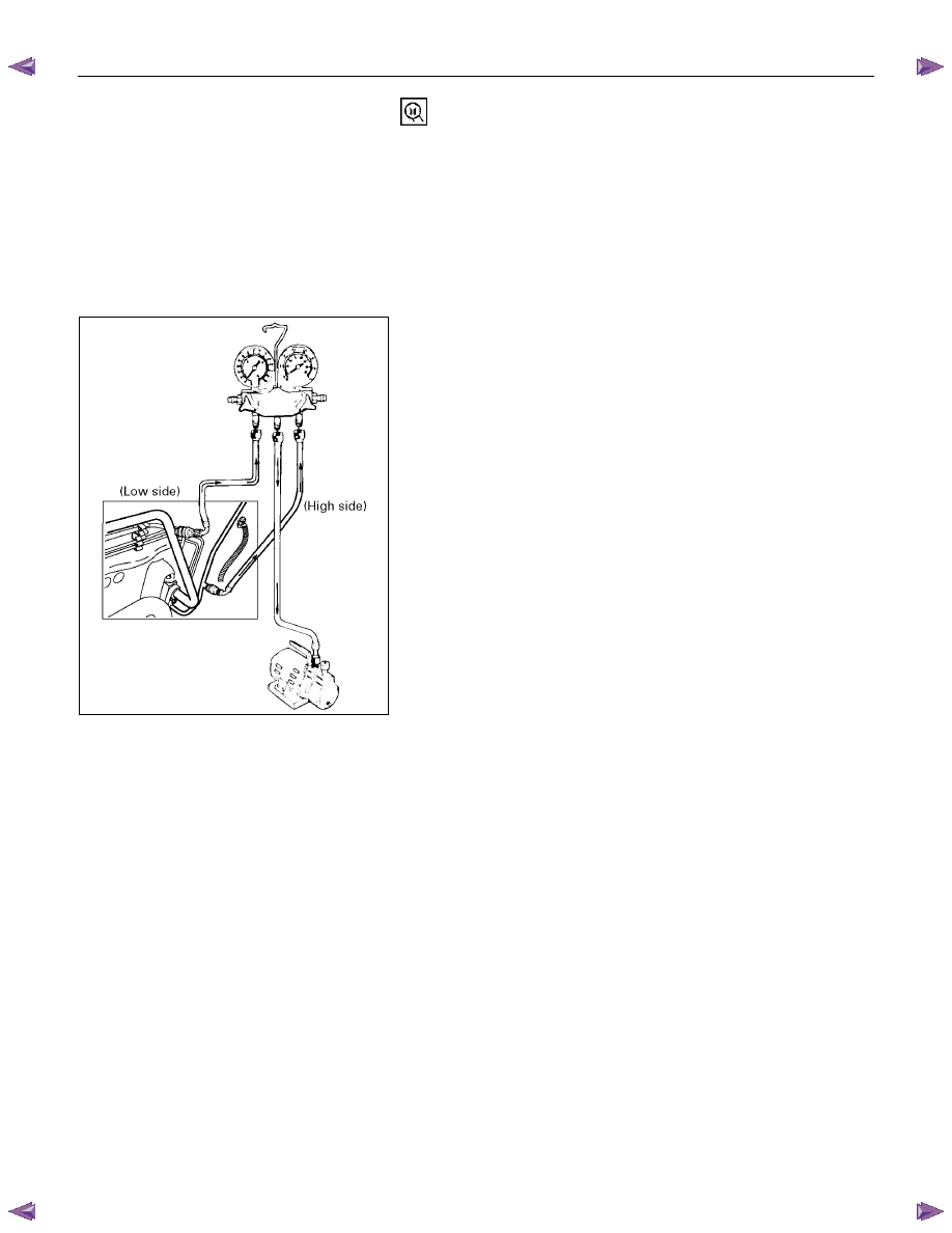
EVACUATION OF THE REFRIGERANT
SYSTEM
NOTE:
Explained below is a method using a vacuum pump. Refer
to the ACR
4
(or equivalent) Manufacturer's Instructions
when evacuating the system with ACR
4
(or equivalent).
Air and moisture in the refrigerant will cause problems in the air
conditioning system.
Therefore, before charging the refrigerant, be sure to evacuate
air and moisture thoroughly from the system.
1) Connect the gauge manifold.
•••• High-pressure valve (HI) - Discharge-side
•••• Low-pressure valve (LOW) - Suction-side
2) Discharge and recover the refrigerant.
3) Connect the center hose of the gauge manifold set to the
vacuum pump inlet.
4) Operate the vacuum pump, open shutoff valve and then
open both hand valves.
5) When the low-pressure gauge indicates approx. 100kPa
(750 mmHg/30 inHg), continue the evacuation for 5 minutes
or more.
6) Close both hand valves and stop the vacuum pump.
7) Check to ensure that the pressure does not change after 10
minutes or more.
•••• If the pressure changes, check the system for leaks.
•••• If leaks occur, retighten the refrigerant line connections
and repeat the evacuation steps.
8) If no leaks are found, again operate the vacuum pump for
20 minutes or more. After confirming that the gauge
manifold pressure is at 100 kPa (750 mmHg/30 inHg), close
both hand valves.
9) Close positive shutoff valve.
Stop the vacuum pump and disconnect the center hose
from the vacuum pump.
HEATER AND AIR CONDITIONING 1-35
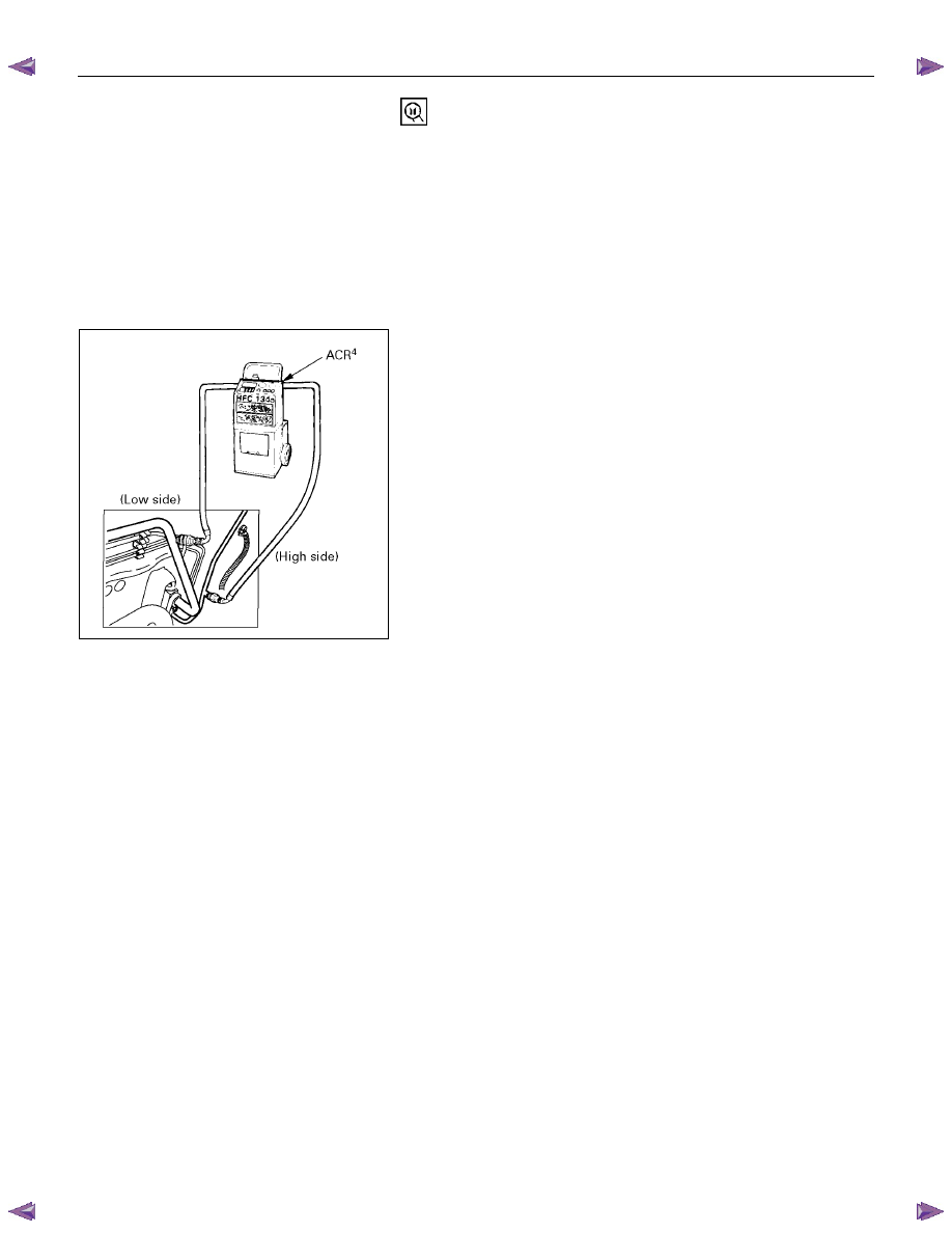
CHARGING THE REFRIGERANT SYSTEM
There are various methods of charging refrigerant into the air
conditioning system.
These include using the ACR
4
(HFC-134a Refrigerant
Recovery/ Recycling/Recharging/System) or equivalent and
direct charging with a manifold gauge charging station.
ACR
4
(115V 60Hz) : 5-8840-0629-0 (J-39500-A)
ACR
4
(220-240V 50/60Hz)
:
5-8840-0630-0
(J-39500-220A)
ACR
4
(220-240V 50/60Hz Australian model)
:
5-8840-0631-0
(J-39500-220ANZ)
F06R300012
Charging procedure
•••• ACR
4
(or equivalent) method
For the charging of refrigerant recovered by ACR
4
, follow the
Manufacturer's Instruction.
1-36 HEATER AND AIR CONDITIONING
F06R300013
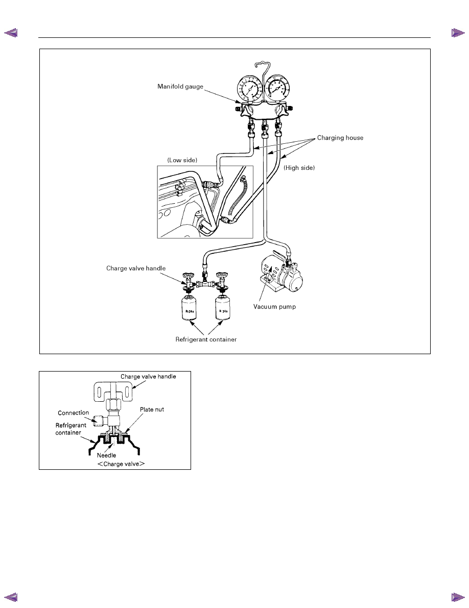
•••• Direct charging with a manifold gauge charging
station method.
Handling the charging valve handle when installing refrigerant
container.
1) Before attaching the charge valve to the refrigerant
container, turn the charge valve handle counterclockwise
until the needle is fully retracted.
2) Turn the plate nut counterclockwise until it reaches its
highest position relative to the charge valve.
3) Install the charge valve onto the refrigerant container.
4) Turn the plate nut clockwise and connect the center hose of
the manifold gauge to the charge valve.
5) Tighten the plate nut sufficiently by hand. Then turn the
charge valve handle clockwise to lower the needle and bore
a hole in the refrigerant container.
6) Turn the charge valve handle counterclockwise to raise the
needle. The refrigerant in the refrigerant container is
charged into the air conditioning system by the operation of
the manifold gauge.
•••• Be absolutely sure not to reuse the emptied

HEATER AND AIR CONDITIONING 1-37
refrigerant container.
1) Make sure the evacuation process is correctly completed.
2) Connect the center-hose of the manifold gauge to the
refrigerant container.
•••• Turn the charge valve handle counterclockwise to purge
to the charging line and purge any air exiting in the
center-hose of the manifold gauge.
3) Open the low-pressure hand valve and charge the
refrigerant about 200 g (0.44 lbs.).
•••• Make sure the high-pressure hand valve is closed.
•••• Avoid charging the refrigerant by turning the refrigerant
container upside down.
4) Close the low-pressure hand valve of the manifold gauge.
•••• Check to ensure that the degree of pressure does not
change.
5) Check the refrigerant leaks by using a HFC-134a leak
detector.
•••• If a leak occurs, repair the leak connection, and start all
over again from the first step of evacuation.
6) If no leaks are found, open the low-pressure hand valve of
the manifold gauge. Then continue charging refrigerant to
the system.
•••• When charging the system becomes difficult:
(1) Run the engine at Idling and close the all vehicle
doors.
(2) A/C switch is "ON".
(3) Set the fan control knob (fan switch) to its highest
position.
(4) Set air source selector lever to “RECIRC”
WARNING
BE ABSOLUTELY SURE NOT TO OPEN THE HIGH-
PRESSURE HAND VALVE. SHOULD THE HIGH-
PRESSURE HAND VALVE BE OPENED, THE HIGH-
PRESSURE REFRIGERANT GAS WOULD FLOW
BACKWARD, AND THIS MAY CAUSE THE REFRIGERANT
CONTAINER TO BURST.
7) When the refrigerant container is emptied, use the following
procedure to replace it with a new refrigerant container.
(1) Close the low-pressure hand valve.
(2) Raise the needle upward and remove the charge valve.
(3) Reinstall the charge valve to the new refrigerant
container.
(4) Purge any air existing in the center hose of the manifold
gauge.
Нет комментариевНе стесняйтесь поделиться с нами вашим ценным мнением.
Текст