Isuzu KB P190. Manual — part 18

1-38 HEATER AND AIR CONDITIONING
8) Charge the system to the specified amount and then close
the low-pressure hand valve.
Refrigerant
Amount
g(lbs)
4JA1-T, 4JH1-TC, C24SE
720 (1.59)
4JJ1-TC (Standard Output)
4JJ1-TC (High Output)
4JK1-TC (High Output)
650 (1.43)
9) Check for refrigerant leaks by using a HFC-134a leak
detector.
• A fully charged system is indicated by the sight glass on
the receiver/drier being free of any bubbles (Refer to
"Reading Sight Glass").
• Check the high and low pressure value of the manifold
gauge. (Refer to “CHECKING REFRIGERANT SYSTEM
WITH MAINFOLD GAUGE” in SERVICE
INFORMATION.)
Immediately after charging refrigerant, both high and low
pressures are slightly high and to the left of the gauge, but they
settle down to the guide pressure valves as shown below:
• Ambient temperature; 30∼35°C (86∼95°F)
• Guide
pressure
High-pressure
side;
Approx.
1373
∼1670 kPa (14∼17 kg/cm
2
/ 199
∼242 psi)
Low-pressure
side;
Approx.
127
∼245 kPa (1.3∼2.5 kg/cm
2
/ 18
∼36 psi)
10) Close the low pressure hand valve and charge valve of the
refrigerant container.
11) Stop the air conditioning and the engine.
12) Disconnect the high and low pressure hoses from the
manifold gauge fittings.
HEATER AND AIR CONDITIONING 1-39
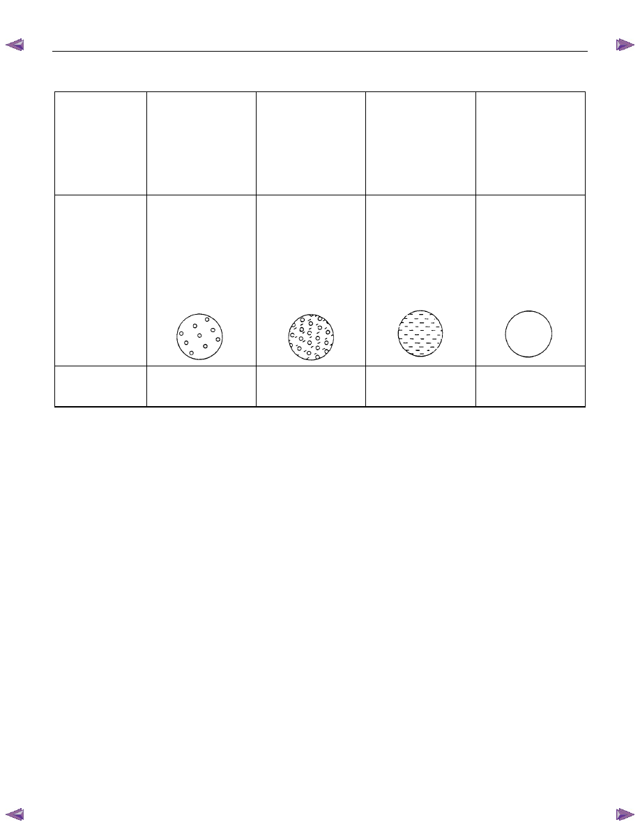
Reading Sight Glass
High and low
pressure pipe
temperature
The high pressure
pipe is hot and the
low pressure pipe
is cold. There is a
distinct difference
in temperature
between them.
The high pressure
pipe is warm and
the low pressure
pipe is cool. There
is no great
difference in
temperature
between them.
There is little
difference in
temperature
between the high
pressure pipe and
the low pressure
pipe.
The high pressure
pipe is hot and the
low pressure pipe
is slightly warm.
There is a
difference in
temperature
between them.
Sight glass
condition
Almost transparent.
A flow of bubbles
can be seen, but
they disappear
when the throttle is
opened.
A flow of bubbles
always can be
seen. It appears
sometimes
transparent, and
sometimes frothy.
Something like fog
faintly can be seen.
Even at idle with
the fan at "HI" (with
the window fully
open), the bubbles
cannot be seen.
Air conditioning
cycle condition
OK
NG
(Not enough
refrigerant)
NG
(Almost no
refrigerant)
NG
(Too much
refrigerant)
The sight glass provides accurate diagnosis only under the following conditions.
If the vehicle can be tested under these conditions, check the sight glass appearance and compare to the chart.
* Engine speed Idling
* A/C switch "ON"
* Blower fan operating at highest speed
* Air source selector lever at "RECIRC"
* Temperature control knob at coldest position
* Ambient temperature below 35
°C (95°F) and humidity below 70% (See NOTE 1)
* High side pressure less than 1470 kPa (15 kg/cm
2
/ 213 psi) (See NOTE 2)
NOTE 1
If the vehicle cannot be moved to a testing location that meets these specifications, then the sight glass cannot be
used for diagnosis. You must discharge and recover the refrigerant, then recharge the system with the specified
amount of refrigerant. Then continue checking the system performance.
NOTE 2
If the high side pressure is greater than stated, the sight glass cannot be used for diagnosis. You must discharge
and recover the refrigerant, then recharge the system with the specified amount of refrigerant. Then continue
checking system performance.
1-40 HEATER AND AIR CONDITIONING
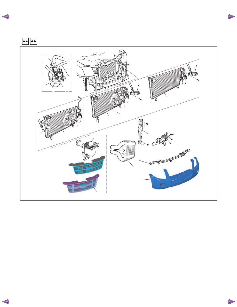
CONDENSER
REMOVAL AND INSTALLATION (4JH1-TC, 4JJ1-TC Standard Output)
13
12
8
10
11
14
10
9
6
7
5
2
3
1
4
14
10
4JH1-TC
4JJ1-TC
Standard Output
(RHD)
14
10
4JJ1-TC
Standard Output
(LHD)
9
This illustration is based on RHD model
RTW710LF001401
Removal Steps
1. Radiator grille
2. Front bumper fascia
• Refer to SECTION 2A “FRONT
BUMPER”
3. Front bumper impact support assembly
• Refer to SECTION 2A “FRONT
BUMPER”
4. Air cleaner assembly
5. Inter cooler
• Refer to SECTION 6A “INTER COOLER”
6. Engine hood lock
7. Engine hood front end stay
8. Pressure switch connector
9. Condenser fan connector
10. Refrigerant line
11. Refrigerant line
12. Receiver/drier bracket
13.
Receiver/drier
14. Condenser assembly
Installation Steps
14. Condenser assembly
13.
Receiver/drier
12. Receiver/drier bracket
11. Refrigerant line
10. Refrigerant line
9. Condenser fan connector
8. Pressure switch connector
7. Engine hood front end stay
6. Engine hood lock
5. Inter cooler
• Refer to SECTION 6A “INTER COOLER”
4. Air cleaner assembly
3. Front bumper impact support assembly
• Refer to SECTION 2A “FRONT
BUMPER”
2. Front bumper fascia
• Refer to SECTION 2A “FRONT
BUMPER”
1. Radiator grille
HEATER AND AIR CONDITIONING 1-41
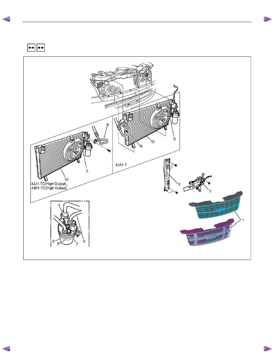
REMOVAL AND INSTALLATION (4JJ1-TC High Output, 4JK1-TC High Output, 4JA1-T)
This illustration is based on RHD model
RTW710LF001501
Removal Steps
1. Radiator grille
2. Engine hood lock
3. Engine hood front end stay
4. Pressure switch connector
5. Condenser fan connector
6. Refrigerant line
7. Refrigerant line
8. Receiver/drier bracket
9.
Receiver/drier
10. Condenser assembly
Installation Steps
10. Condenser assembly
9.
Receiver/drier
8. Receiver/drier bracket
7. Refrigerant line
6. Refrigerant line
5. Condenser fan connector
4. Pressure switch connector
3. Engine hood front end stay
2. Engine hood lock
1. Radiator grille
Нет комментариевНе стесняйтесь поделиться с нами вашим ценным мнением.
Текст