Isuzu KB P190. Manual — part 374
6A-136 ENGINE MECHANICAL (4JK1/4JJ1)
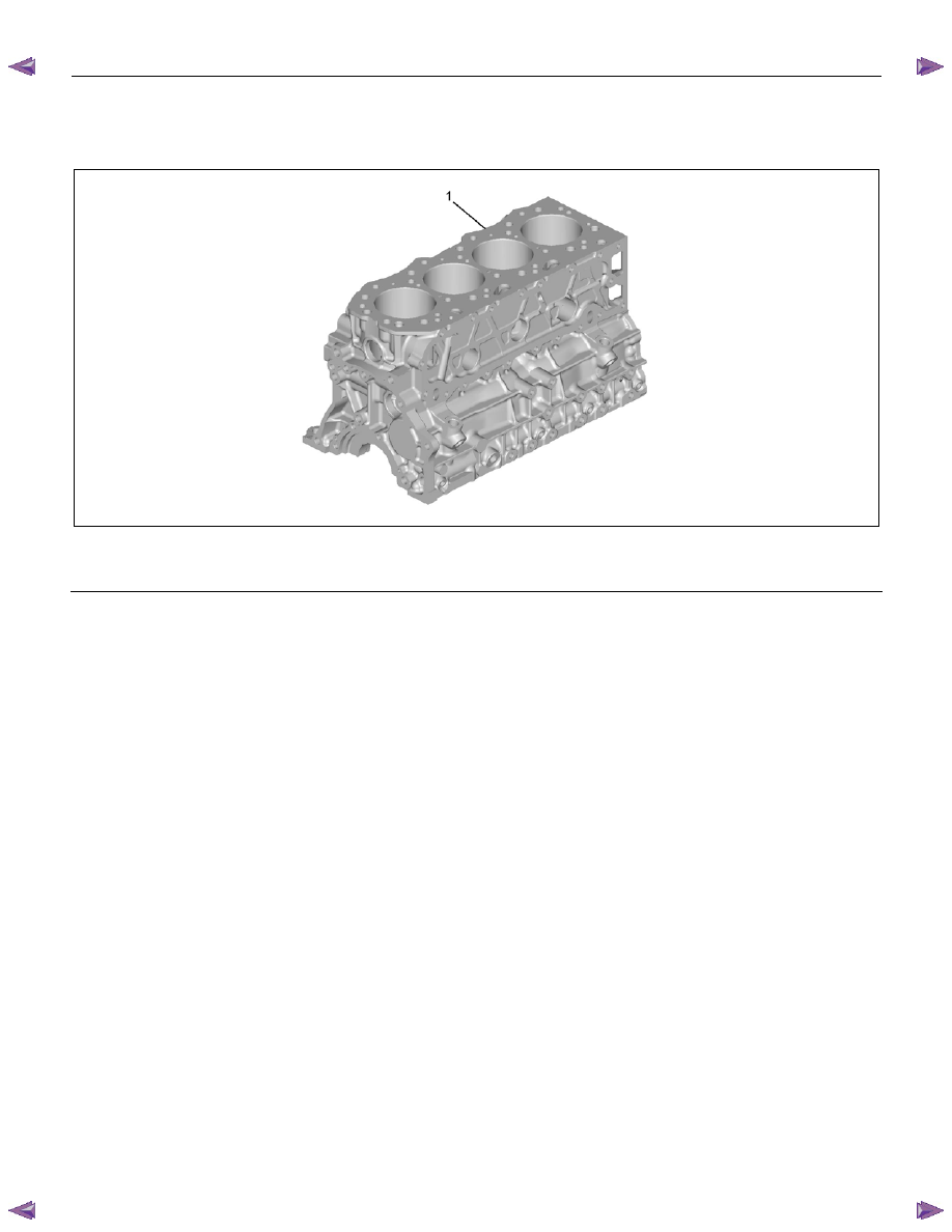
Cylinder Block
Components
RTW76ASF000101
Legend
1. Cylinder
Block
Removal
1. Demount the engine assembly.
Refer to "Engine Assembly".
2. Remove the cylinder head cover.
Refer to "Cylinder Head Cover".
3. Remove the camshaft assembly.
Refer to "Camshaft Assembly".
4. Remove the cylinder head.
Refer to "Cylinder Head".
5. Remove the fuel supply pump and fuel rail
assembly.
Refer to "Fuel Supply Pump" and "Fuel Rail
Assembly" in FUEL SYSTEM Section.
6. Remove the oil filter assembly and oil cooler.
Refer to “Oil Filter Assembly and Oil Cooler”.
7. Remove the crankshaft front oil seal.
Refer to "Crankshaft Front Oil Seal".
8. Remove the crankshaft rear oil seal.
Refer to "Crankshaft Rear Oil Seal".
9. Remove the oil pan.
Refer to "Oil Pan".
10. Remove the water pump.
Refer to "Water Pump" in Cooling System Section.
11. Remove the front cover.
Refer to "Front Cover".
12. Remove the timing gear train.
Refer to "Timing Gear Train".
13. Remove the oil pump.
Refer to "Oil Pump".
14. Remove pistons and connecting rods.
Refer to "Piston and Connecting Rod".
15. Remove the crankshaft.
Refer to "Crankshaft".
ENGINE MECHANICAL (4JK1/4JJ1) 6A-137
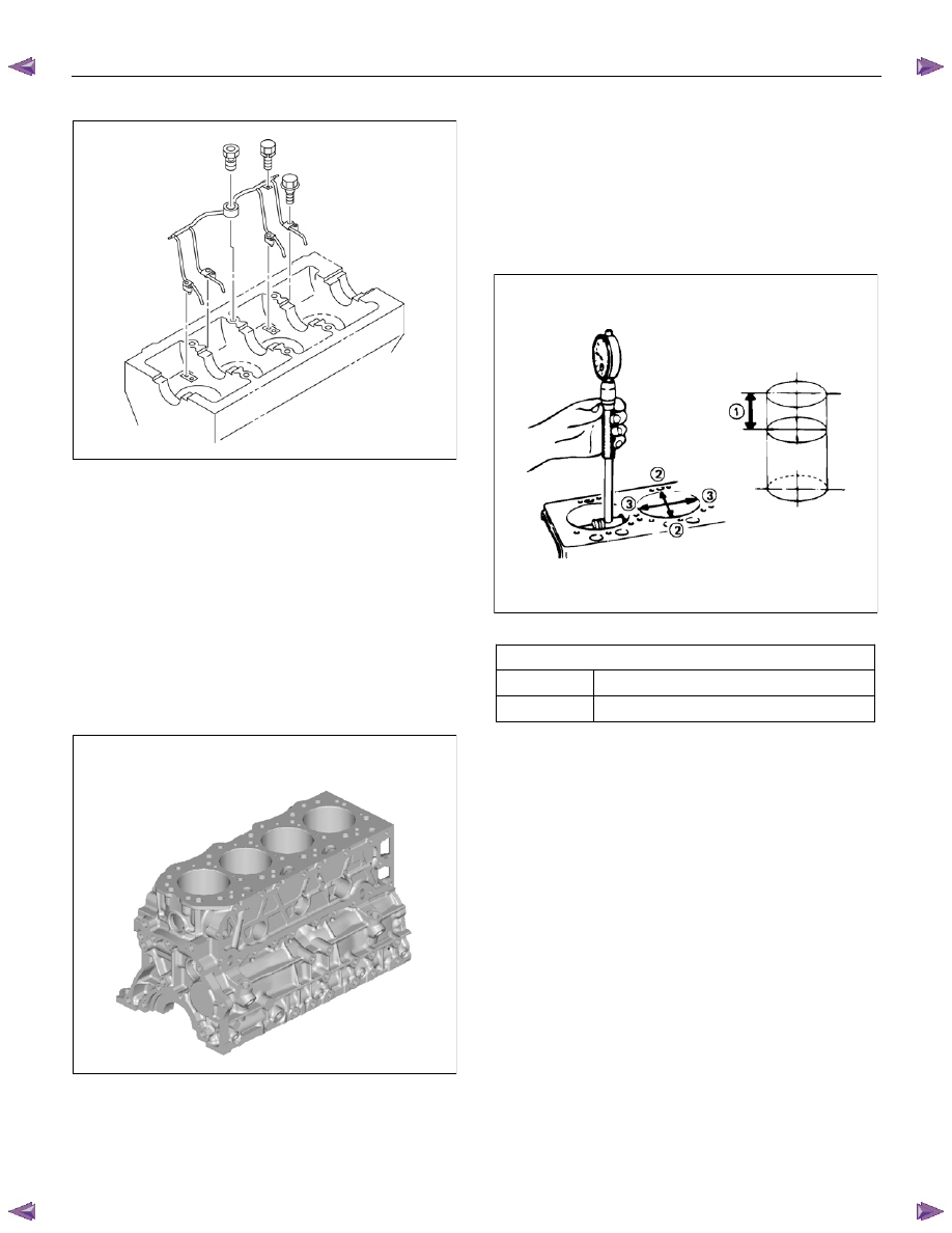
16. Remove the piston cooling pipe.
RTW76ASH001101
Inspection
1. Carefully remove water stains or other foreign
matters on the surface of the cylinder block.
• Be careful not to damage the cylinder block.
2. Carefully remove the liquid gasket on the
crankcase mounting surface.
3. Clean up the cylinder block.
4. Visually inspect the cylinder block.
• Conduct color check and hydraulic (or
pneumatic) test and if you find a crack or other
damage, replace the cylinder block.
RTW76ASH000801
5. Cylinder block wear measurement.
• Use a cylinder indicator to measure the cylinder
bore at measuring point (1) in the thrust (2-2)
and axial (3-3) directions of the crankshaft.
• Measuring Point (1): 20 mm (0.79 in)
If the measured value exceeds the specified
limit, the cylinder block must be replaced or
rebored.
012RY00010
Cylinder block bore diameter
mm (in)
Standard 95.421
− 95.450 (3.7567 − 3.7579)
Limit 95.48
(3.7590)
6A-138 ENGINE MECHANICAL (4JK1/4JJ1)
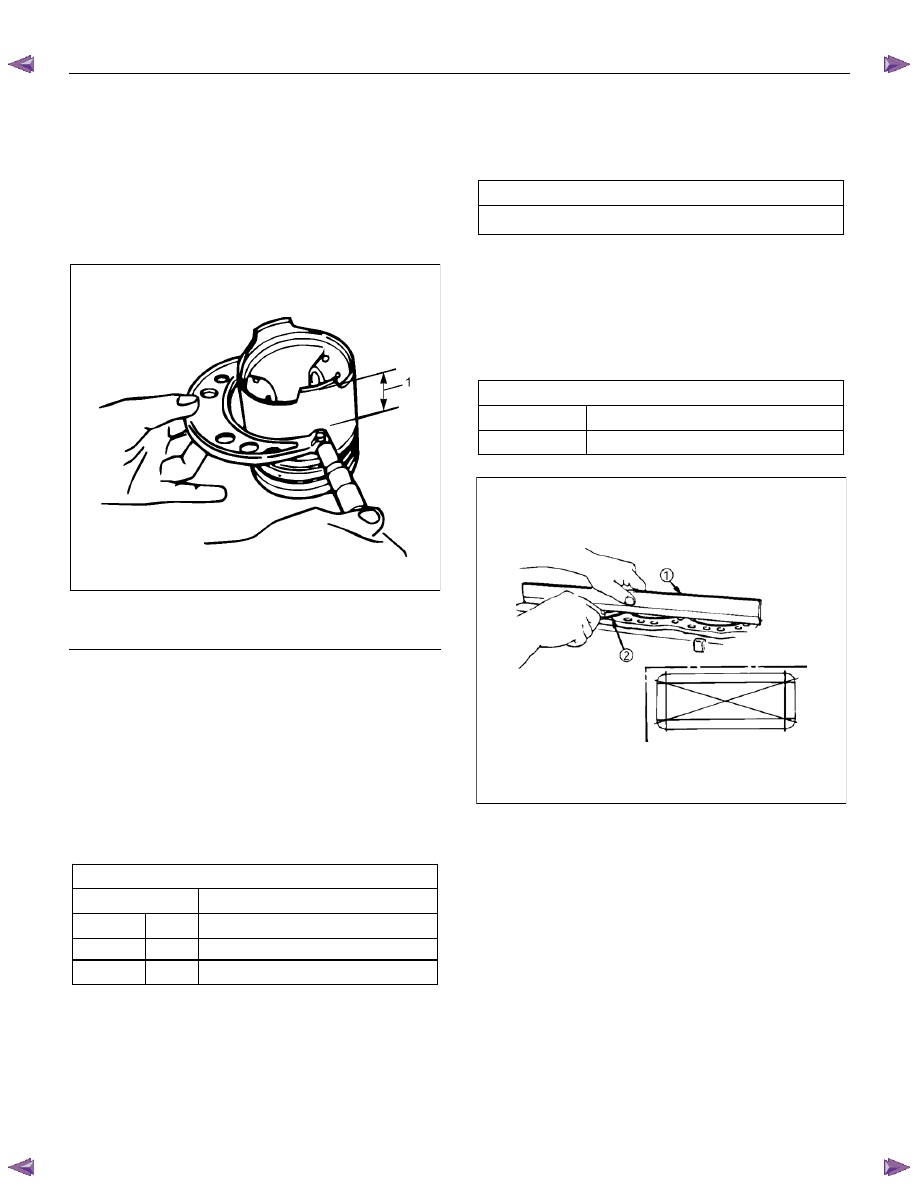
6. Cylinder Reboring.
• Select oversize pistons to fit the largest cylinder
bore (previously measured).
• At a point 11 mm (0.43 in) above the lower
edge of the piston skirt, measure the piston
diameter at a right angle to the piston pin.
Calculate the additional cylinder boring required
for each cylinder.
RTW56ASH023101
Legend
1. 11mm
(0.43in)
• Formula
Boring inside diameter = D + C - H ± E
D = Piston outside diameter
(Measured Oversize Piston)
C = Piston and cylinder bore clearance
0.082 - 0.100 mm (0.0032 - 0.0039 in)
H = Honing allowance
0.03 mm (0.0012 in) or less
E = Boring machine error
Piston size
mm (in)
Standard
95.330 - 95.359 (3.7531 - 3.7543)
Oversize (0.25) 95.580 - 95.609 (3.7629 - 3.7641)
(0.50) 95.830 - 95.859 (3.7728 - 3.7739)
(0.75) 96.080 - 96.109 (3.7826 - 3.7838)
• Bore and hone the individual cylinders as
required.
• Once again, measure the individual cylinder
bores.
Each cylinder bore remainder
mm (in)
0.02 (0.0008) or less.
7. Cylinder block upper face warpage.
• Use a straight edge (1) and a thickness gauge
(2) to measure the four sides and the two
diagonals of the cylinder block upper face.
• If the measured values exceeds the limit, the
cylinder block must be replaced.
Cylinder block upper face warpage
mm (in)
Standard
0.05 or less (0.002 or less)
Limit 0.20
(0.0080)
012R100001
ENGINE MECHANICAL (4JK1/4JJ1) 6A-139
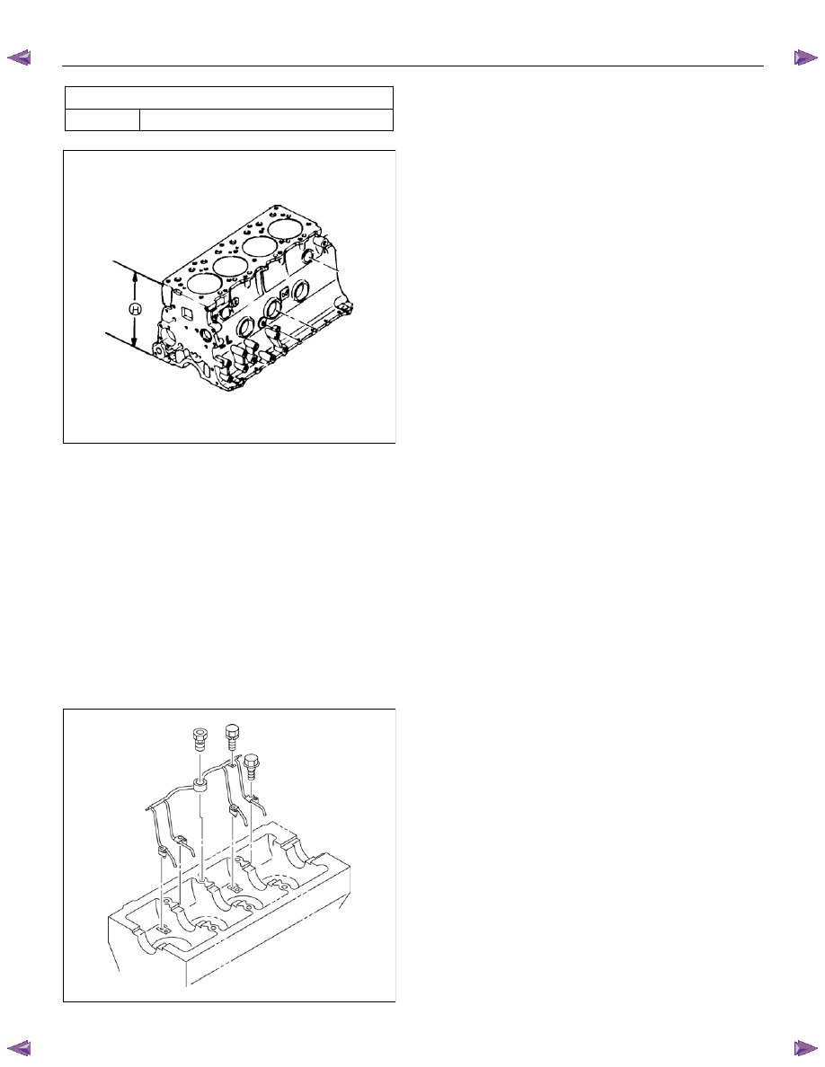
Cylinder block height (H) (Reference)
mm (in)
Standard
259.945 – 260.055 (10.2340 – 10.2384)
012R100009
Installation
1. Install the piston cooling pipe.
• Align the dowel pin of the piston cooling pipe
with the pin hole on the cylinder block and
tighten with the relief valve.
Tightening torque:
Relief valve 30 N
⋅⋅⋅⋅m (3.1 kg⋅⋅⋅⋅m / 22 lb ft)
bolts M8
25 N
⋅⋅⋅⋅m (2.5 kg⋅⋅⋅⋅m / 18 lb ft)
bolts M6
8 N
⋅⋅⋅⋅m (0.8 kg⋅⋅⋅⋅m / 69 lb in)
Note:
Be careful not to deform or damage the piston cooling
pipe nozzle.
RTW76ASH001101
2. Install the crankshaft.
Refer to "Crankshaft".
3. Install pistons and connecting rods.
Refer to "Piston and Connecting Rod".
4. Install the oil pump.
Refer to "Oil Pump".
5. Install the timing gear train.
Refer to "Timing Gear Train".
6. Install the front cover.
Refer to "Front Cover".
7. Install the water pump.
Refer to "Water Pump" in Cooling System Section.
8. Install the oil pan.
Refer to "Oil Pan".
9. Install the crankshaft rear oil seal.
Refer to "Crankshaft Rear Oil Seal".
10. Install the crankshaft front oil seal.
Refer to "Crankshaft Front Oil Seal".
11. Install the oil filter assembly and oil cooler.
Refer to "Oil Filter Assembly and Oil Cooler".
12.
Install the fuel supply pump and fuel rail
assembly.
Refer to "Fuel Supply Pump" and "Fuel Rail
Assembly " in Fuel System Section.
13. Install the cylinder head.
Refer to "Cylinder Head".
14. Install the camshaft assembly.
Refer to "Camshaft Assembly".
15. Install the cylinder head cover.
Refer to "Cylinder Head Cover".
16. Mount the engine assembly on the chassis.
Refer to "Engine Assembly".
Нет комментариевНе стесняйтесь поделиться с нами вашим ценным мнением.
Текст