Isuzu KB P190. Manual — part 354
6A-56 ENGINE MECHANICAL (4JK1/4JJ1)
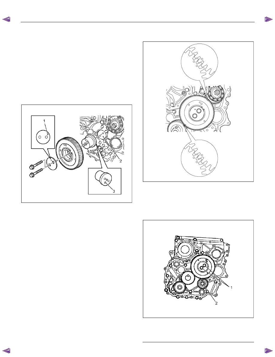
• Align the oil hole of the cylinder body (2) with
the oil hole of the idle gear A shaft (3).
• Install the flange so that the front mark (1) face
toward the front.
• Install the idle gear A and idle gear A flange,
idle gear A shaft at the position shown in the
figure.
• Apply engine oil over the part where the gear of
the idle gear shaft is to be put together.
• Apply engine oil to the bolt screw thread and
seat, and temporarily tighten together with the
flange (tighten fully in later process).
LNW71BSH000501
• Attach, aligning with the gear crank: idle A and
timing mark.
RTW56ALH000301
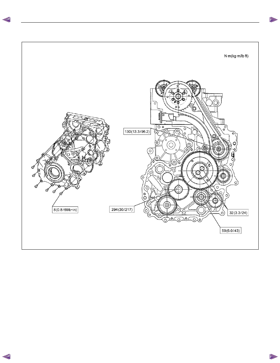
5. Tighten the bolts of idle gear A and idle gear C to
the specified torque.
Tightening torque:
idle gear A 32 N
⋅⋅⋅⋅m (3.3 kg⋅⋅⋅⋅m / 24 lb ft)
idle gear C 59 N
⋅⋅⋅⋅m (6.0 kg⋅⋅⋅⋅m / 43 lb ft)
RTW56ASH011701
Legend
1. Idle Gear A Bolt
2. Idle Gear C Bolt
ENGINE MECHANICAL (4JK1/4JJ1) 6A-57
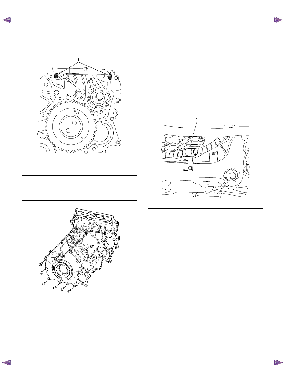
6. Remove the M6 bolt from the idle gear A.
7. Install the gear case cover.
• Apply the liquid gasket (ThreeBond TB-1207B
or equivalent).
RTW56ASH020101
Legend
1. Apply the liquid gasket
• Install the gasket in slot of the gear case cover.
• Tighten the bolts to the specified torque.
Tightening torque: 8 N
⋅⋅⋅⋅m (0.8 kg⋅⋅⋅⋅m / 69 lb in)
RTW56ASH012101
8. Install the vacuum pump.
Tightening torque: 25 N
⋅⋅⋅⋅m (2.5 kg⋅⋅⋅⋅m / 18 lb ft)
• Install the oil pipe (feed side and return side) of
vacuum pump.
• Install the vacuum pipe bracket and vacuum
pipe.
9. Install the power steering pump.
• Tighten the nuts to the specified torque.
Tightening torque: 25 N
⋅⋅⋅⋅m (2.5 kg⋅⋅⋅⋅m / 18 lb ft)
• Connect the bracket (1) of power steering oil
hose.
LTW56ASH000101
10. Install the crank pulley.
Tightening torque: 294 N
⋅⋅⋅⋅m (30.0 kg⋅⋅⋅⋅m / 217 lb ft)
11. Install the A/C compressor drive belt and fan belt.
Refer to drive belt tension check procedure for
Heating and air conditioning and Engine cooling in
this manual.
12. Install the cooling fan.
13. Install the fan guide.
14. Install the radiator upper hose.
15. Replenish the engine coolant.
6A-58 ENGINE MECHANICAL (4JK1/4JJ1)
Torque Specifications
LNW76ALF000601
ENGINE MECHANICAL (4JK1/4JJ1) 6A-59
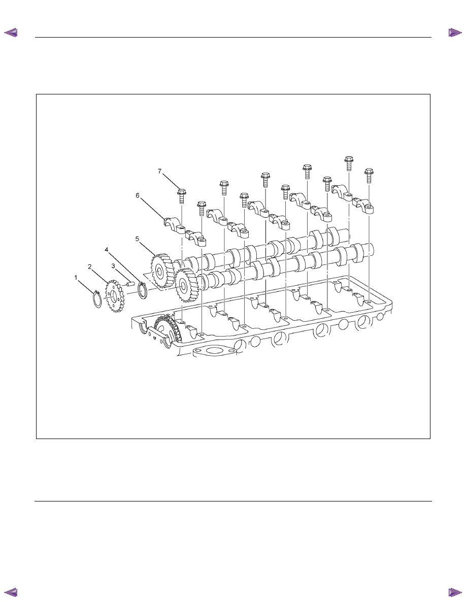
Camshaft Assembly
Components
RTW56ALF000901
Legend
1. Snap
Ring
2. Sub
Gear
3. Knock
Pin
4. Damper
Spring
5. Camshaft Gear and Camshaft
6. Camshaft Bearing Cap
7. Bolt
Нет комментариевНе стесняйтесь поделиться с нами вашим ценным мнением.
Текст