Isuzu KB P190. Manual — part 353

6A-52 ENGINE MECHANICAL (4JK1/4JJ1)
LTW56ASH000101
8. Remove the vacuum pump.
• Remove the vacuum pipe bracket and vacuum
pipe.
• Remove the oil pipe (feed side and return side)
of vacuum pump.
RTW76ASH000201
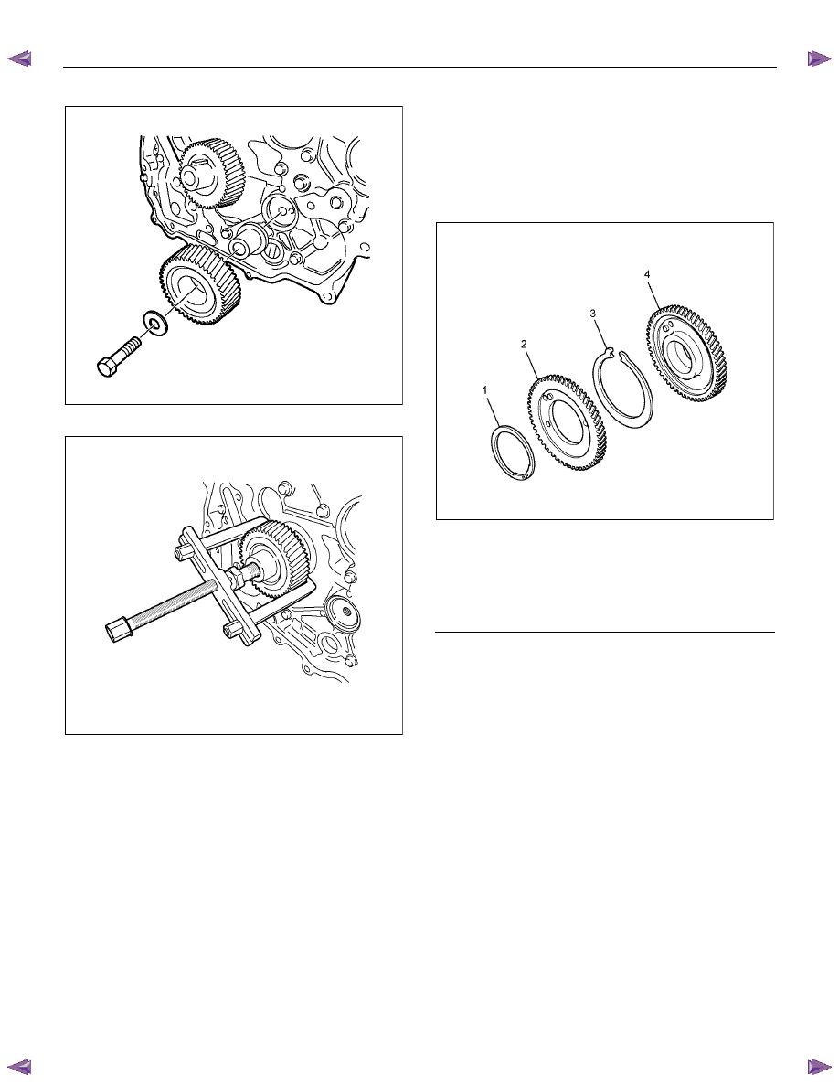
9. Remove the front cover.
RTW56ASH019701
10. Install the M6 bolt to the idle gear A.
11. Remove the idle gear A and idle gear A flange, idle
gear A shaft.
RTW56ASH011301
ENGINE MECHANICAL (4JK1/4JJ1) 6A-53
12. Remove the idle gear C and idle gear C shaft.
RTW56ASH011401
13. Remove the crankshaft gear.
RTW56ASH021501
Disassembly
1. Remove the scissor gear assembly.
• Clamp the vise. Insert soft metal protectors
(aluminum) between the vise and component.
Use a pair of snap ring pliers to remove the
scissor gear assembly.
RTW56ASH022001
Legend
1. Snap
Ring
2. Sub-gear
3. Spring
4. Idle Gear A
Reassembly
1. Install the scissor gear assembly.
• Clamp the vise. Insert soft metal protectors
(aluminum) between the vise and component.
Press against the pin on the left side of the idle
gear A spring to make a gap on the right side of
the spring. Push the spring into place.
6A-54 ENGINE MECHANICAL (4JK1/4JJ1)
• Align the sub gear pin with the hole in the right
side of the idle gear A spring. Press the sub-
gear into place.
RTW56ASH022001
Legend
1. Snap
Ring
2. Sub-gear
3. Spring
4. Idle Gear A
• Use a pair of snap ring pliers to snuggly install
the snap ring.
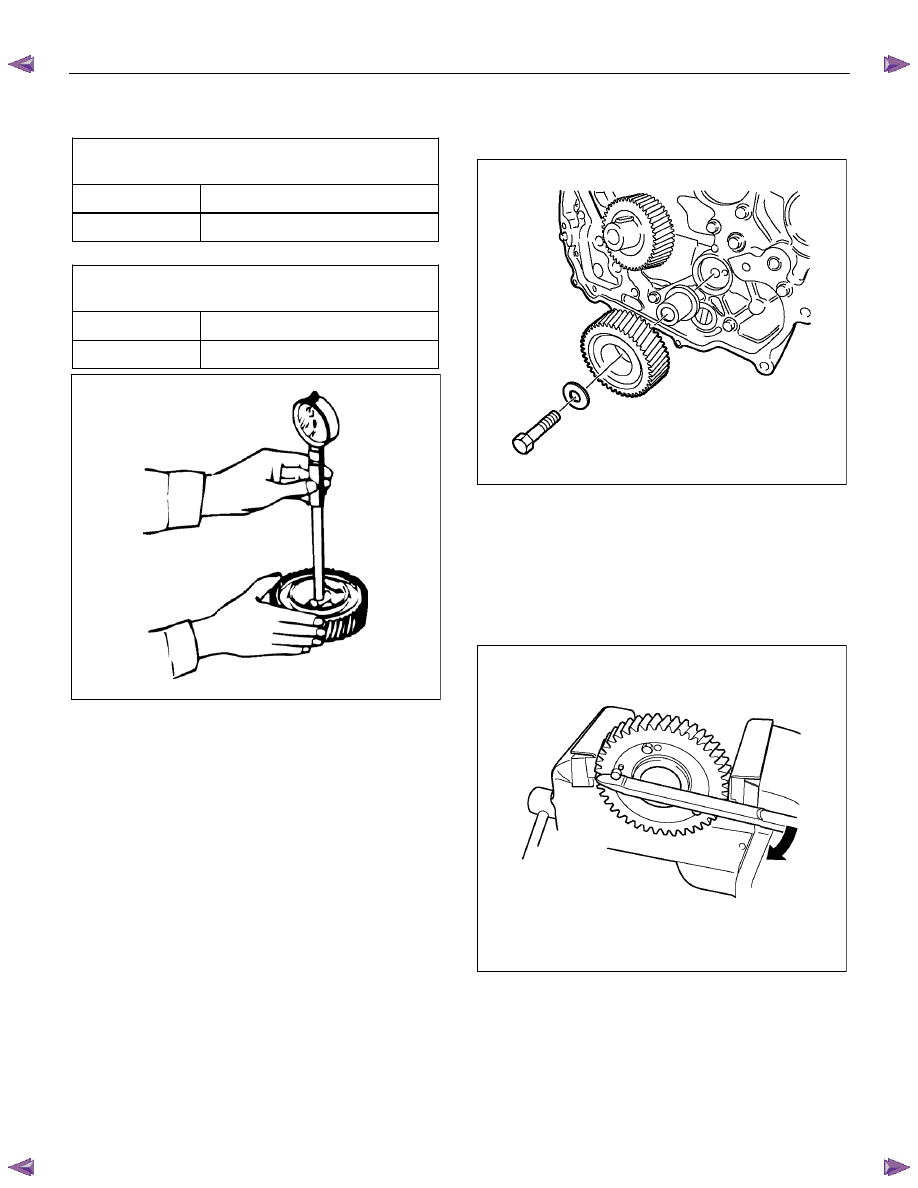
Inspection
1. Measurement of idle gear backlash
• Apply a dial gauge on the teeth of the idle gear
to be measured and move the gear to right and
left lightly to read how much the dial gauge
shook (never fail to fix the gear).
• If the measurement exceeds the limit, replace
the idle gear.
Backlash of the idle gear
mm (in)
Standard 0.10
− 0.17 (0.004 − 0.006)
Limit 0.30
(0.01)
• Measure backlash of the idle gear before
removing the idle gear A.
2. Measurement of end clearance of the idle gear.
• Insert a thickness gauge between the idle gear
and the thrust collar to measure a clearance.
• If the measurement exceeds the limit, replace
either the idle gear or the thrust collar.
End clearance of the idle gear
mm (in)
Standard 0.080
− 0.155 (0.003 − 0.006)
Limit 0.20
(0.008)
• Measure an end clearance of the idle gear
before removing the idle gear B.
3. External diameter of the idle gear shaft.
• Use a micrometer to measure an external
diameter of each idle gear shaft.
• If the measurement exceeds the limit, replace
the shaft.
External diameter of the idle gear A shaft
mm (in)
Standard 44.950
− 44.957 (1.7697 − 1.7700)
Limit 44.80
(1.764)
External diameter of the idle gear C shaft
mm (in)
Standard 24.959
− 24.980 (0.9826 − 0.9835)
Limit 24.80
(0.976)
RTW56ASH021601
4. Clearance between the idle gear and the idle gear
shaft
• Measure an inside diameter of the idle gear
bush to calculate a clearance between the idle
gear and the idle gear shaft.
ENGINE MECHANICAL (4JK1/4JJ1) 6A-55
• If the measurement exceeds the limit, replace
either the idle gear or the shaft.
Clearance between the idle gear A and the shaft
mm
(in)
Standard 0.020
− 0.062 (0.0007 − 0.0024)
Limit 0.200
(0.0079)
Clearance between the idle gear C and the shaft
mm
(in)
Standard 0.025
− 0.075 (0.0010 − 0.0030)
Limit 0.200
(0.0079)
LNW21BSH003601
Installation
1. Install the crankshaft gear.
2. Install the idle gear C.
• Apply engine oil over the part where the gear of
the idle gear shaft is to be put together.
• Apply engine oil to the bolt screw thread and
seat, and temporarily tighten together with the
flange (tighten fully in later process).
RTW56ASH011401
3. Install the idle gear A.
4. Tighten sub gear setting bolt.
• Use the M6 bolts and lever to turn sub gear to
right direction until it aligns with the M6 bolt
hole between idle gear A and sub gear.
• Tighten the M6 bolt to a suitable torque to
prevent the sub gear from moving.
RTW56ASH011501
Нет комментариевНе стесняйтесь поделиться с нами вашим ценным мнением.
Текст