Isuzu KB P190. Manual — part 89
FRONT SUSPENSION 3C-35
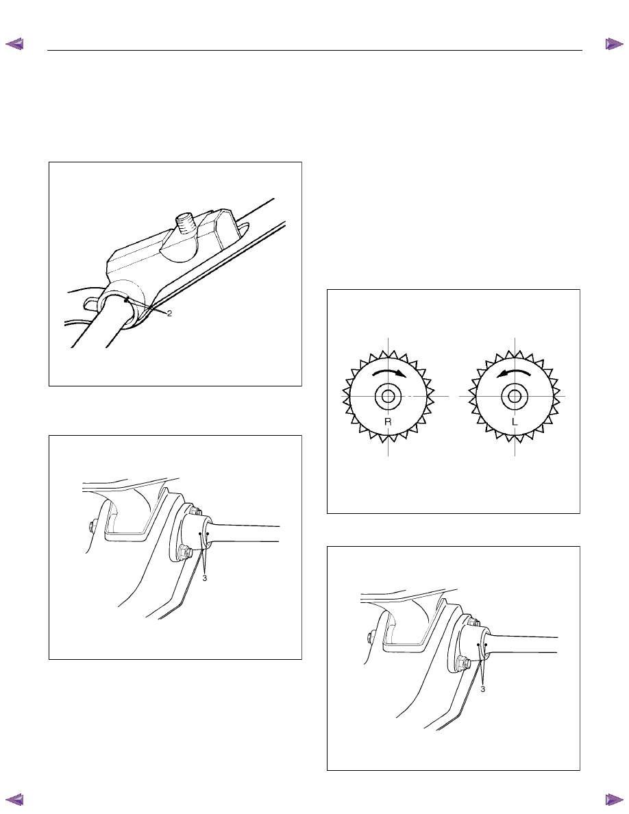
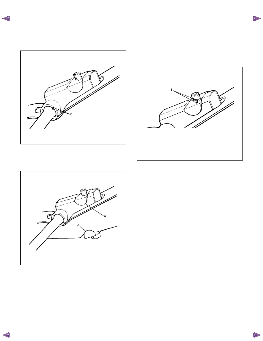
3. Apply the setting marks (2) to the height control
arm and torsion bar, then remove height control
arm.
NOTE: “Besco chassis grease” should be applied on
contact area of height control arm with frame.
(RH & LH Both side)
410RS005
4. Apply the setting marks (3) to the torsion bar and
lower control arm, and then remove torsion bar.
RTW340SH000301
Inspection and Repair
Make necessary correction or replace parts if wear,
damage, corrosion or any other abnormal condition is
found through inspection.
Check the following parts:
• Torsion
bar
• Height control arm
• Adjust
bolt
• Rubber seat
Installation
1. Apply grease to the serrated portions, then install
torsion bar. Make sure the bars are on their correct
respective sides and align the setting marks (3).
410RS007
RTW340SH000301
3C-36 FRONT SUSPENSION
2. Apply grease to the portion that fits into the bracket
then install height control arm and align the setting
marks (2).
410RS005
3. Apply grease to the bolt portion of the end piece
(4). Apply grease to the portion of the seat (5) that
fits into the bracket.
410RS008
4. Apply grease to the serrated portions.
5. Install adjust bolt and seat, then turn the adjust bolt
to the setting mark (1) applied during disassembly.
NOTE: Adjust the trim height. Refer to Front End
Alignment Inspection and Adjustment in Steering
section.
410RS004
FRONT SUSPENSION 3C-37
Knuckle
Knuckle and Associated Parts
RUW63CLF000101
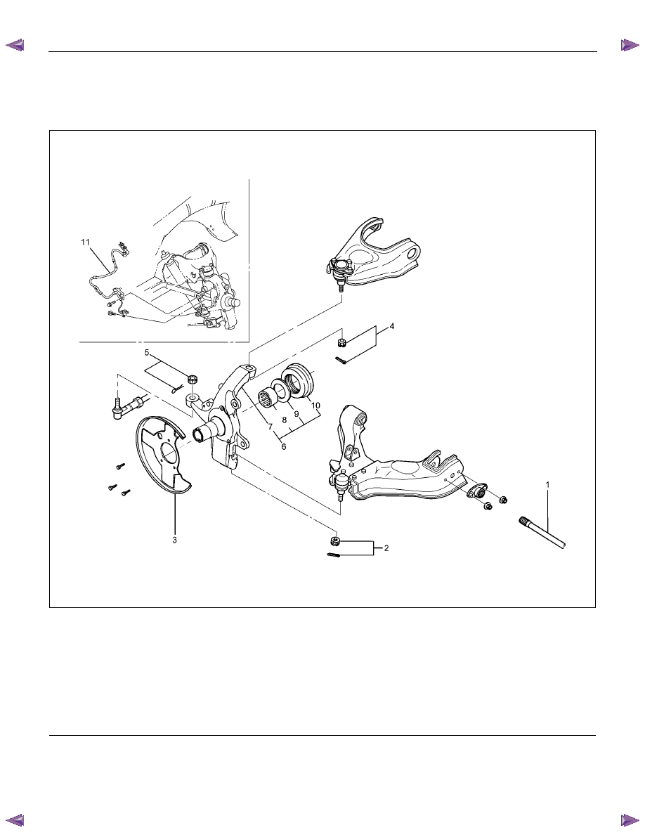
Legend
(1) Torsion Bar
(2) Nut and Cotter Pin, Lower Ball Joint
(3) Back Plate
(4) Nut and Cotter Pin, Upper Ball Joint
(5) Nut and Cotter Pin, Tie-rod End
(6) Knuckle Assembly
(7)
Knuckle
(8) Needle Bearing (4
×4 Model Only)
(9) Thrust Washer (4
×4 Model Only)
(10) Oil Seal (4
×4 Model Only)
(11) Speed Sensor harness
Removal
1. Raise the vehicle and support the frame with
suitable safety stands.
2. Remove wheel and tire assembly. Refer to Wheel
in this section.
3. Remove the brake caliper. Refer to Disc Brakes in
Brake section.
3C-38 FRONT SUSPENSION
4. Remove the hub assembly. Refer to Front Hub
and Disk in this section.
5. Remove tie-rod end from the knuckle. Refer to
Power Steering Unit in Steering section.
6. Remove the speed sensor from the knuckle.
7. Loosen torsion bar by height control arm adjust
bolt, and then remove torsion bar. Refer to Torsion
Bar in this section.
8. Remove speed sensor harness.
9. Remove back plate.
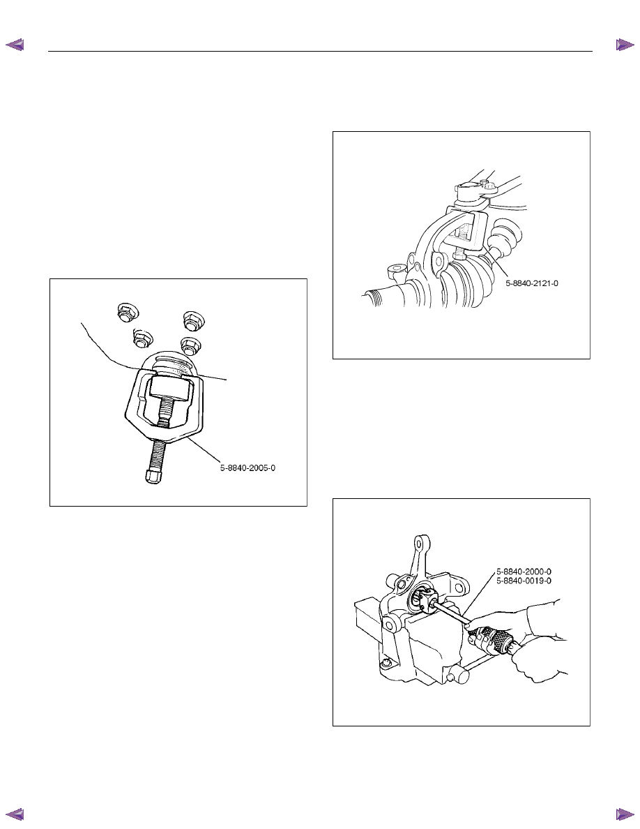
10. Remove lower ball joint by using remover 5-8840-
2005-0.
CAUTION: Be careful not to damage the ball joint
boot.
901RW271
11. Remove upper ball joint by using remover 5-8840-
2121-0.
CAUTION: Be careful not to damage the ball joint
boot.
901RW272
12. Remove knuckle assembly.
13.
Remove oil seal. If replacement required.
(4
×4 Model Only)
14.
Remove washer. If replacement required.
(4
×4 Model Only)
15. Remove needle bearing by using remover 5-8840-
2000-0 and sliding hammer 5-8840-0019-0.
If replacement required. (4
×4 Model Only)
(4
×4 Model Only)
RTW340SH00401
Нет комментариевНе стесняйтесь поделиться с нами вашим ценным мнением.
Текст