Isuzu KB P190. Manual — part 90
FRONT SUSPENSION 3C-39
Inspection and Repair
Make necessary correction or replace parts if wear,
damage, corrosion or any other abnormal condition is
found through inspection.
Check the following parts:
• Knuckle
• Thrust washer (4×4 Model Only)
Installation
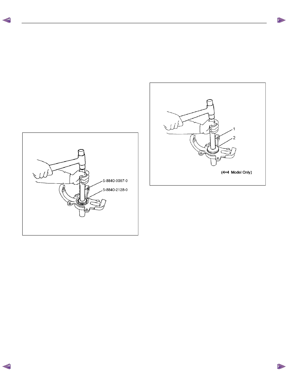
1. Apply appropriate amount of multipurpose type
grease to the new bearing (Approx. 5 g (0.18 oz))
and install needle bearing by using installer 5-
8840-2128-0 and grip 5-8840-0007-0. (4
×4 Model
Only)
(4
×4 Model Only)
901RW275
2. Apply multipurpose type grease to the thrust
washer, and install washer with chamfered side
facing knuckle. (4
×4 Model Only)
3. Use a new oil seal, and apply multipurpose type
grease to the area surrounded by the lip (approx. 2
g (0.07 oz)). Then use installer 5-8840-2851-0 (2)
and grip 5-8840-0007-0 (1) to install oil seal. After
fitting the oil seal to the installer, drive it to the
knuckle using a hammer or bench press until the
tool front face contacts with the thrust washer.
(4
×4 Model Only)
RTW73CSH000101
4. Install knuckle assembly.
5. Install upper ball joint and tighten the nut to the
specified torque, with just enough additional torque
to align cotter pin holes. Install new cotter pin.
Torque: 98 N
⋅⋅⋅⋅m (10.0 kgf⋅⋅⋅⋅m/72 lb⋅⋅⋅⋅ft)
6. Install lower ball joint and tighten the nut to the
specified torque, with just enough additional torque
to align cotter pin holes. Install new cotter pin.
Torque: 147 N
⋅⋅⋅⋅m (15.0 kgf⋅⋅⋅⋅m/108 lb⋅⋅⋅⋅ft)
7. Install back plate.
8. Install speed sensor harness.
9. Install torsion bar; refer to Torsion Bar in this
section.
NOTE: Adjust the trim height. Refer to Front End
Alignment Inspection and Adjustment in Steering.
3C-40 FRONT SUSPENSION
Upper Control Arm
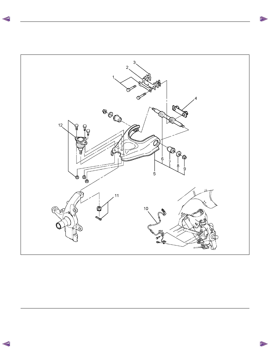
Upper Control Arm and Associated Parts
RTW440LF001301
Legend
(1) Bolt and Plate
(2) Camber Shims
(3) Caster Shims
(4) Nut Assembly
(5) Upper Control Arm Assembly
(6) Fulcrum Pin
(7)
Bushing
(8)
Plate
(9) Upper Control Arm Nut
(10) Speed Sensor harness
(11) Nut and Cotter Pin
(12) Upper Ball Joint, Bolt and Nut
Removal
1. Raise the vehicle and support the frame with
suitable safety stands.
2. Remove wheel and tire assembly. Refer to Wheel
in this section.
3. Remove the brake caliper and disconnect brake
pipe. Refer to Disc Brakes in Brake section.
FRONT SUSPENSION 3C-41
4. Support lower control arm with a harness.
5. Remove speed sensor harness.
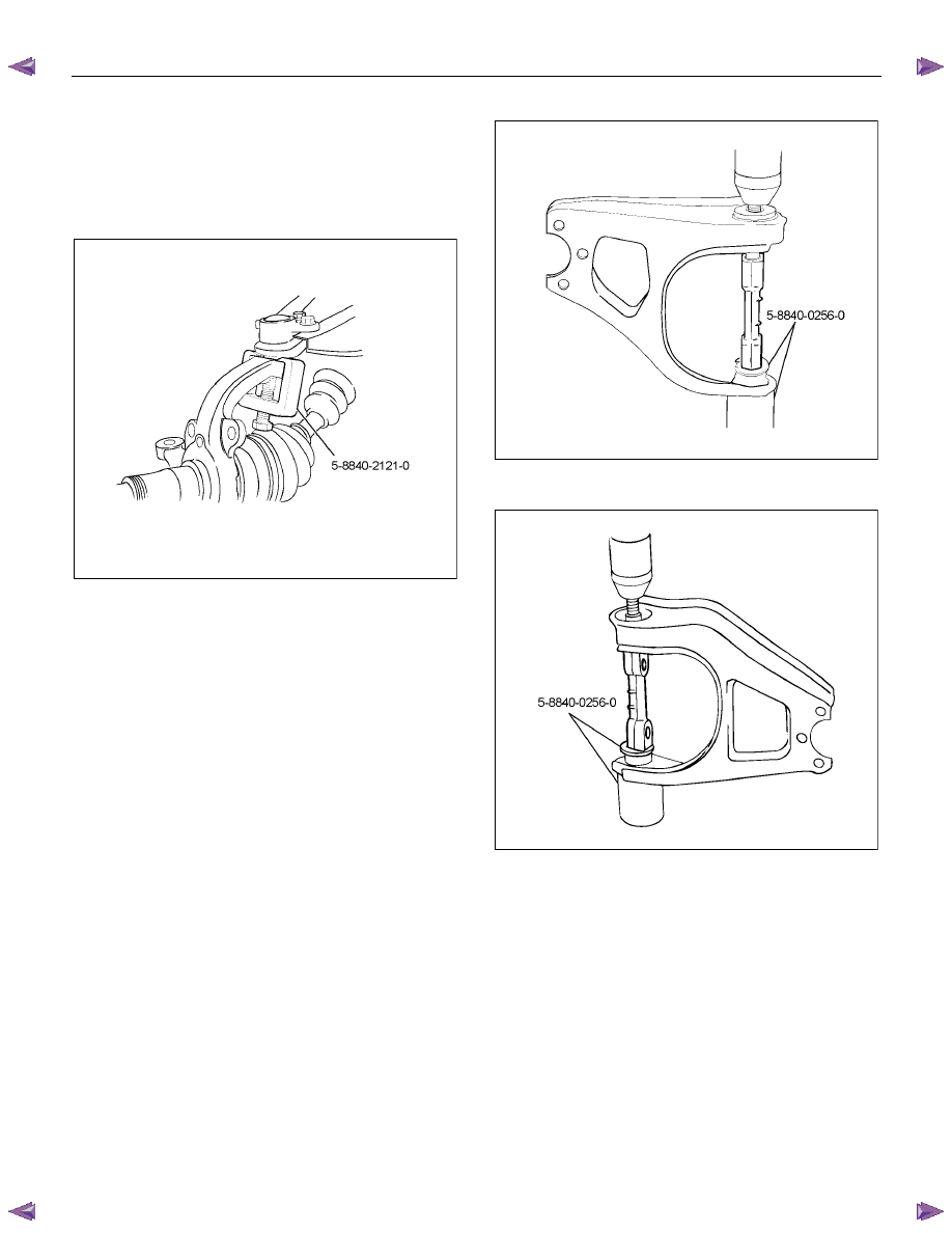
6. Remove nut and cotter pin then remove knuckle
using remover 5-8840-2121-0.
CAUTION: Be careful not to damage the ball joint
boot.
RTW340SH000401
7. Remove upper ball joint.
8. Remove bolt and plate.
9. Remove nut assembly.
10. Remove camber shims and note the positions and
number of shims.
11. Remove caster shims and note the positions and
number of shims.
12. Remove upper control arm assembly.
13. Remove upper control arm nut.
14. Remove plate.
15. Remove bushing by using remover 5-8840-0256-0.
RTW340SH000501
RTW340SH000601
16. Remove fulcrum pin.
Inspection and Repair
Make necessary parts replacement if wear, damage,
corrosion or any other abnormal conditions are found
through inspection.
Check the following parts:
• Upper control arm
• Bushing
• Fulcrum pin
3C-42 FRONT SUSPENSION
Installation
1. Install fulcrum pin.
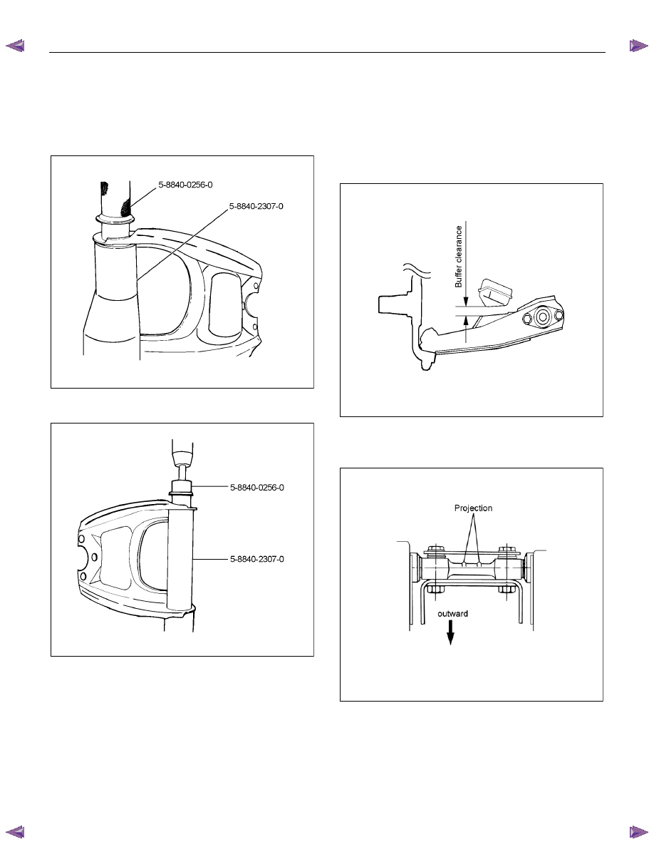
2. Install bushing by using installer 5-8840-0256-0
and 5-8840-2307-0.
RTW340SH000701
RTW340SH000801
3. Install upper ball joint and tighten it to the specified
torque.
Torque: 57 N
⋅⋅⋅⋅m (5.8 kgf⋅⋅⋅⋅m/42 lb⋅⋅⋅⋅ft)
4. Install nut and cotter pin then tighten the nut to the
specified torque, with just enough additional torque
to align cotter pin holes. Install new cotter pin.
Torque: 98 N
⋅⋅⋅⋅m (10.0 kgf⋅⋅⋅⋅m/72 lb⋅⋅⋅⋅ft)
5. Install plate.
6. Install upper control arm nut and tighten fulcrum
pin nut finger-tight.
NOTE: Apply oil to the thread.
NOTE: Tighten the nut with the parts in the position
shown in the illustration below.
Buffer clearance: 29.7 mm (1.17 in)
Torque: 108 N
⋅⋅⋅⋅m (11.0 kgf⋅⋅⋅⋅m/80 lb⋅⋅⋅⋅ft)
RTW53ASH000301
7. Install upper control arm assembly with the fulcrum
pin projections turned inward.
RTW53CSH000101-X
8. Install the caster shims (b) between the chassis
frame and fulcrum pin.
Нет комментариевНе стесняйтесь поделиться с нами вашим ценным мнением.
Текст