Isuzu KB P190. Manual — part 662
Engine Mechanical – V6
Page 6A1–169
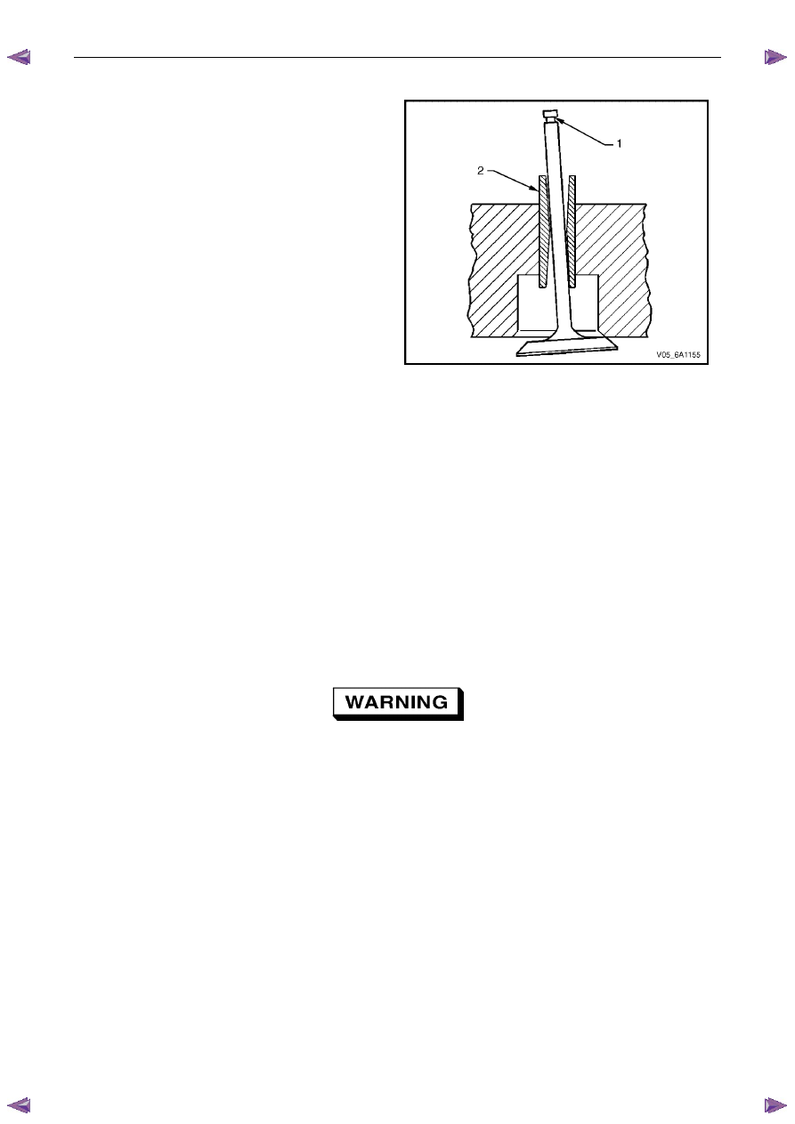
Valve Guide Measurement
1
Measure the valve stem (1) to-guide (2) clearance.
Excessive valve stem-to-guide clearance may cause
excessive oil consumption and may also cause a
valve to break. Insufficient clearance will result in
noisy and sticky functioning of the valve and will
disturb the engine assembly smoothness.
2
Clamp a dial indicator to the cylinder head at the
camshaft cover rail.
3
Locate the dial indicator so the movement of the valve
stem from side to side, crossways to the cylinder
head, will cause a direct movement of the indicator
stem. The dial indicator stem must contact the side of
the valve stem just above the valve guide.
4
Drop the valve head about 0.064 mm off the valve
seat.
5
Use light pressure when moving the valve stem from
side to side to obtain a clearance reading, refer to 5
Specifications.
•
If the clearance for the valve is greater than
specified and a new standard diameter valve
stem will not bring the clearance within
specifications, the valve guide may be oversized
by 0.075 mm using the valve guide reamer, Tool
No. J 42096 or by 0.375 mm using the valve
guide reamer, Tool No. EN-46120. Two sizes of
oversized valve stems are available for service.
•
Valve guide wear at the bottom 10 mm of the
valve guide is not significant enough to affect
normal operation.
•
If over sizing the guide does not bring the
clearance within specifications, replace the
cylinder head.
Figure 6A1 – 289
Valve Spring Inspection and Measurement
Inspection Procedure
1
Clean the valve springs in solvent.
Safety glasses must be worn when using
compressed air
2
Dry the valve springs with compressed air.
3
Inspect the valve springs for broken coils or coil ends.
Engine Mechanical – V6
Page 6A1–170
Measurement Procedure
1
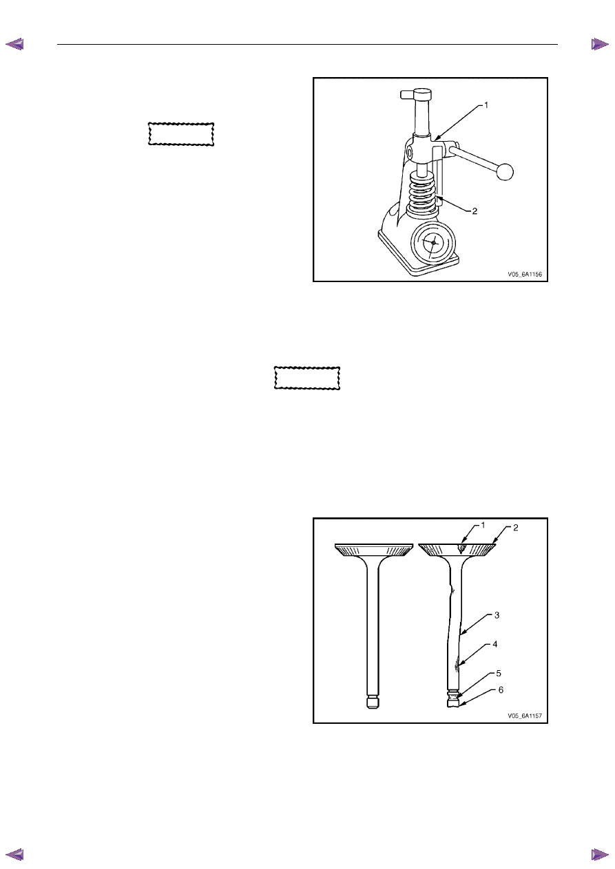
Use a commercially available valve spring tester to
measure the valve spring tension, refer to 5
Specifications.
CAUTION
Do not use shims to increase spring load.
The use of shims can cause the valve spring
to bottom out before the camshaft lobe is at
peak lift.
2
If low valve spring load is found, replace the valve
springs.
Figure 6A1 – 290
Valve and Seat Grinding
Valve Cleaning Procedure
CAUTION
Do not use a wire brush on any part of the
valve stem. The valve stem is chrome plated
to provide enhanced wear characteristics.
Wire brushing the stem could remove the
chrome plating.
1
Use soft bristle brush to clean any carbon build-up from the valve head.
2
Thoroughly clean the valve with solvent and wipe dry.
Valve Visual Inspection Procedure
1
Inspect the valve for damage from the head to tip for
the following conditions:
•
pitting in the valve seat area (1),
•
lack of valve margin (2),
•
bending in the valve stem (3),
•
pitting or excessive wear in the stem (4),
•
worn valve key grooves (5), and
•
worn valve tip (6).
2
Replace the valve if any of these conditions exist.
Figure 6A1 – 291
Valve Measurement and Reconditioning Overview
Correct valve service is critical to engine performance. Therefore, all detailed measurement procedures must be followed
to identify components that are out of specification. If the measurement procedures reveal the valve or valve seat must
be reconditioned, it is critical to perform the measurement procedures after reconditioning.
Engine Mechanical – V6
Page 6A1–171
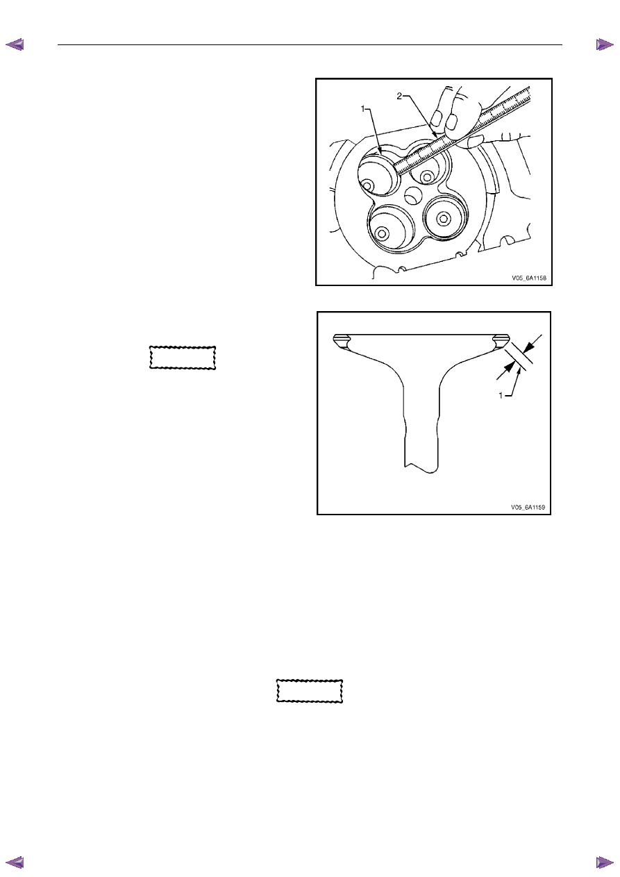
Valve Seat Width Measurement Procedure
1
Measure the valve seat (1) width in the cylinder head
using a scale (2).
Figure 6A1 – 292
2
Measure the seat width on the valve face (1) using a
correct scale.
CAUTION
The seat contact area must be at least
0.5 mm from the outer diameter (margin) of
the valve. If the contact area is too close to
the margins, the seat must be reconditioned
to move the contact area away from the
margin.
3
Compare the measurements with the specifications,
refer to 5
Specifications.
4
If the seat widths are acceptable, check the valve
seat roundness, refer to Valve Seat Roundness
Measurement Procedure in this Section.
5
If the seat width is not acceptable, grind the valve
seat to bring the width back to specification. Correct
valve seat width is critical to providing the correct
amount of valve heat dissipation, refer to Valve and
Seat Reconditioning Procedure in this Section.
Figure 6A1 – 293
Valve Seat Roundness Measurement Procedure
1
Measure the valve seat roundness using a dial indicator attached to a tapered pilot installed in the guide. The pilot
should have a slight bind when installed in the guide.
CAUTION
The correct size pilot must be used. Do not
use adjustable diameter pilots. Adjustable
pilots may damage the valve guides.
2
Compare your measurements with the specifications, refer to 5
Specifications.
3
If the valve seat exceeds the roundness specification, grind the valve and valve seat, refer to Valve and Seat
Reconditioning Procedure in this Section.
4
If new valves are being used, the valve seat roundness must be within 0.05 mm.
Engine Mechanical – V6
Page 6A1–172
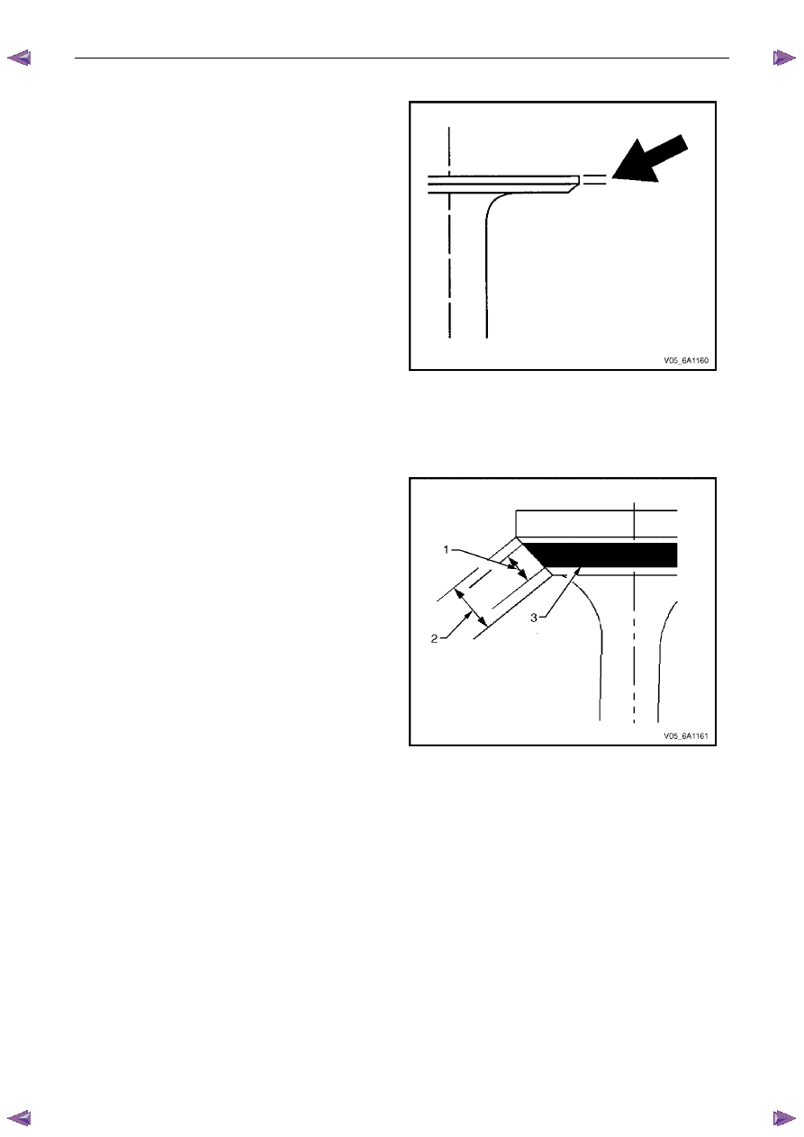
Valve Margin Measurement Procedure
1
Measure the valve margin using an appropriate scale.
2
Refer to 5 Specifications for minimum valve margin
and compare them to your measurements.
3
If the valve margins are beyond specification, replace
the valves.
4
If the valve margins are within specification and do
not require refacing, test the valve for seat
concentricity, refer to Valve-to-Seat Concentricity
Measurement Procedure in this Section.
Figure 6A1 – 294
Valve-to-Seat Concentricity Measurement Procedure
Checking the valve-to-seat concentricity determines whether the valve and seat are sealing correctly.
Measure the valve face and the valve seat to ensure correct valve sealing.
1
Coat the valve face lightly with blue dye (3).
2
Install the valve in the cylinder head.
3
Turn the valve against the seat with enough pressure
to wear off the dye.
4
Remove the valve from the cylinder head.
5
Inspect the valve face.
N O T E
•
If the valve face is concentric, providing a
correct seal, with the valve stem, a continuous
mark (1) will be made around the entire face (2).
•
The wear mark must be at least 0.5 mm from
the margin of the valve. If the wear mark is too
close to the margin, the seat must be
reconditioned to move the contact area away
from the margin.
•
If the face is not concentric with the stem, the
mark will not be continuous around the valve
face. The valve should be refaced or replaced
and the seat must be reconditioned, refer to
Valve and Seat Reconditioning Procedure in
this Section.
Figure 6A1 – 295
Valve and Seat Reconditioning Procedure
If the valve seat width, roundness or concentricity are beyond specifications, grind the seats in order to ensure correct
heat dissipation and prevent the build up of carbon on the seats.
If valve seat reconditioning is required, reface the valve face, unless a new valve is used.
Нет комментариевНе стесняйтесь поделиться с нами вашим ценным мнением.
Текст