Isuzu KB P190. Manual — part 1437
9A1-66 RESTRAINT CONTROL SYSTEM
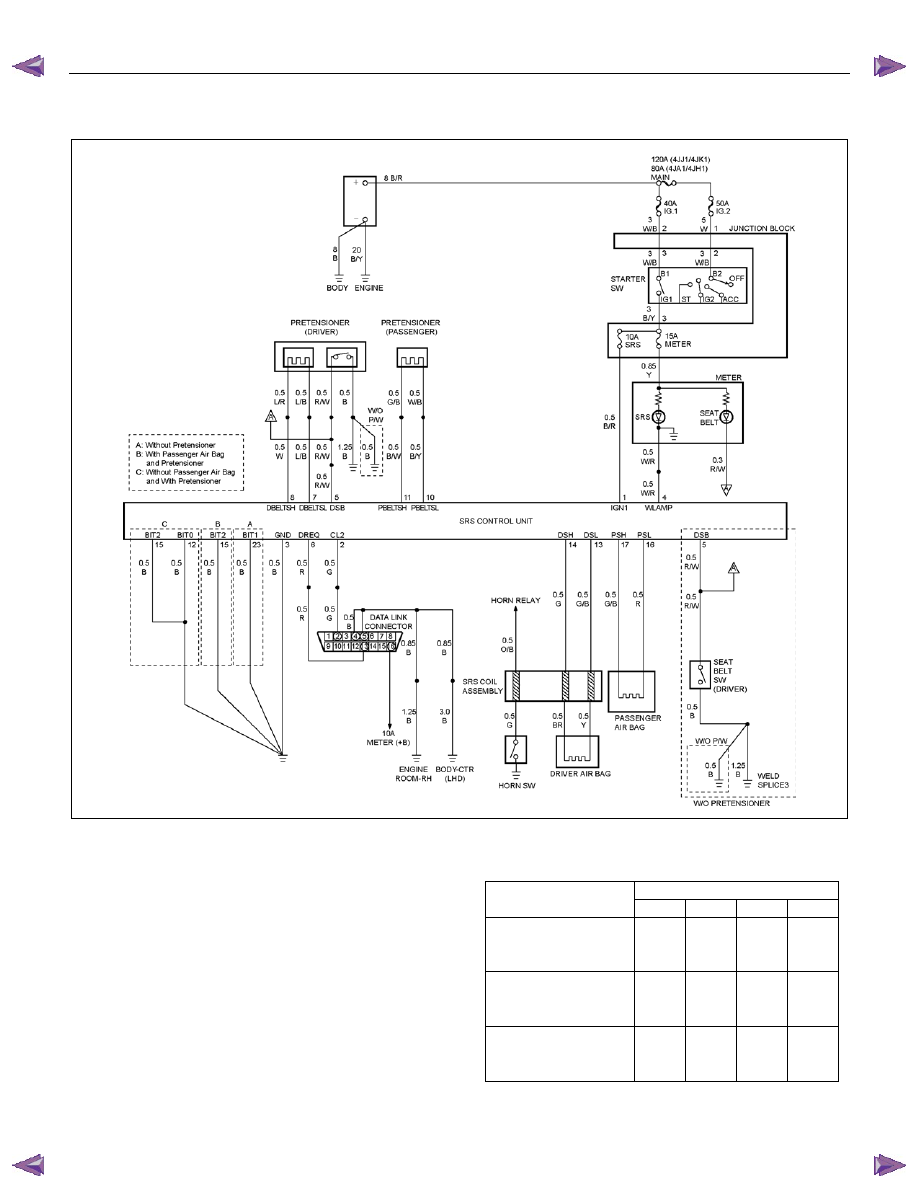
DTC B0055 (Flash Code 55) Vehicle Variant Missing
RTW79ALF000301
Circuit Description
DTC B0055 will be set, if either the SRS control unit or
the SRS control unit harness is not genuine parts.
The correct conditions of terminals on the SRS control
unit and the SRS harness are as follows.
Terminal No.
12 15 23 26
Without
Pretensioner
- -
used
-
With Pretensioner
-
used
-
-
With Pretensioner
and Without
Passenger Air Bg
used used -
-

RESTRAINT CONTROL SYSTEM 9A1-67
Step Action
Yes
No
1
Was the “SRS Diagnostic System Check” performed?
Go to Step 2
Go to the “SRS
Diagnostic System
Check”
2
1. Ignition switch is at “LOCK”.
2. Disconnect the SRS control unit.
3.
Inspect the SRS control unit harness for the following
condition.
Without the pretensioner:
- The wiring harness is not connected on terminal "23"
- The wiring harness is connected on terminals "12", "15"
and "26"
With the pretensioner:
- The wiring harness is not connected on terminal "15"
- The wiring harness is connected on terminals "12", "23"
and "26"
Without the pretensioner and without the passenger air
bag:
- The wiring harness is not connected on terminals "12"
and "15"
- The wiring harness is connected on terminals "23" and
"26"
Was a problem found?
Replace the SRS
control unit
harness.
Go to Step 3
Replace the SRS
control unit.
Go to Step 3
3
1. Reconnect all components and ensure all components are
properly mounted.
2. Clear the diagnostic trouble codes.
Is this step finished?
Go to the “SRS
Diagnostic System
Check”
―
DTC Will Set When
Without the pretensioner:
Terminals "12", "15" and "26" are shorted to
ground.
Terminal "23" is open (harness is not connected).
With the pretensioner:
Terminals "12", "23" and "26" are shorted to
ground.
Terminal "15" is open (harness is not connected).
With the pretensioner and without the passenger
air bag:
Terminals "23" and "26" are shorted to ground.
Terminals "12" and "15" are open (harness is not
connected).
It is DTC set, if non genuine SRS control unit is installed
with the SRS harness genuine part, or incase of
terminal "12", "15", "23" and "26" are abnormal
condition with the SRS control unit genuine part.
Action Taken
The SRS control unit turns “ON" the “SRS" warning
lamp and sets a DTC B0055.
But if there is abnormal condition with the SRS control
unit and/or SRS harness, the DTC is not set.
DTC Will Clear When
DTC B0055 can be cleared only by using the scan tool.
Diagnostic Aids
Ensure that terminal "12" is shorted to ground on the
SRS harness. Terminal "15", "23" and "26" are open
circuit.
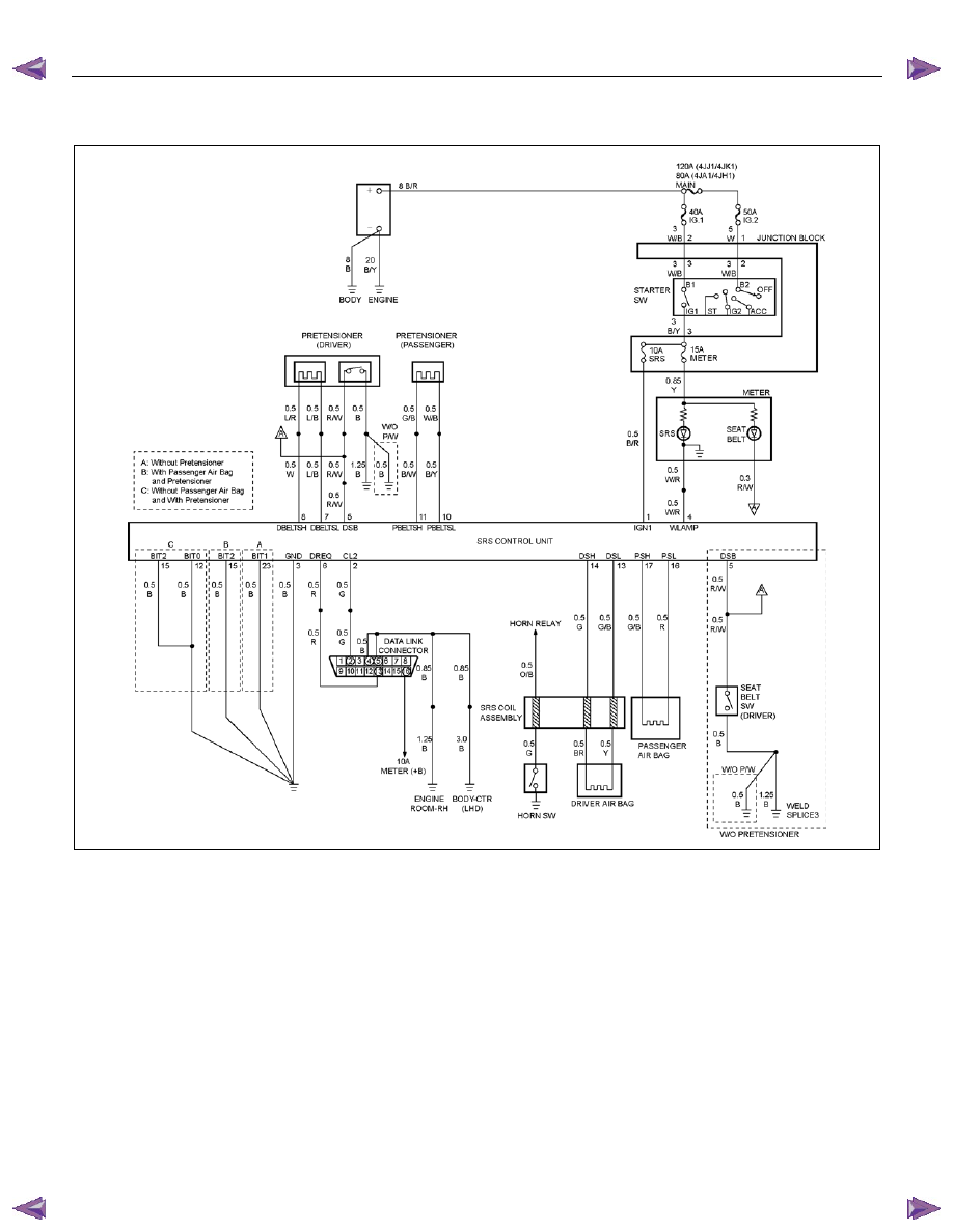
DTC B0055 (Flash Code 55) Vehicle Variant Missing
9A1-68 RESTRAINT CONTROL SYSTEM
DTC B0061 (Flash Code 61) Warning Lamp Circuit Failure
RTW79ALF000301
Circuit Description
When the ignition switch is first turned “ON”, “Ignition 1”
voltage is applied from the “METER” fuse to the “SRS”
warning lamp which is connected to “SRS" warning
lamp, terminal “4”. The “SRS” fuse applies system
voltage to the “Ignition 1” inputs, terminal “1”. The SRS
control unit responds by flashing the “SRS” warning
lamp 7 times. The SRS control unit monitors the “SRS
Warning Lamp" terminal "4" for conditions that are
incorrect for the commanded state of the "SRS" warning
lamp.
For example, a failure condition exists if the SRS
control unit detects low voltage when the "SRS" warning
lamp is commanded OFF, or high voltage when the
"SRS" warning lamp is commanded ON. If the SRS
control unit detects an improper voltage on the “SRS
Warning Lamp" terminal "4", DTC B0061 will set.
DTC Will Set When
The SRS control unit try to turn "ON" the "SRS" warning
lamp but the battery voltage is not supplied to terminal
"4".
The SRS control unit try to turn "OFF" the "SRS"
warning lamp but the battery voltage is supplied to
terminal "4".
Action Taken
If circuits of the “SRS" warning lamp power supply and
ground are normal condition, the SRS control unit turns
“ON” the “SRS” warning lamp and sets a diagnostic
trouble code.

RESTRAINT CONTROL SYSTEM 9A1-69
DTC Will Clear When
The malfunction is no longer occurring and the ignition
is turned to “LOCK”.
DTC Chart Test Description
Number(s) below refer to step number(s) on the
diagnostic chart:
4. This test determines whether the SRS control unit is
malfunctioning
5. This test determines whether the malfunction is in
the “SRS Warning Lamp” circuit.
7. This test determines whether the SRS control unit is
malfunctioning
8. This test determines whether the malfunction is in
the “SRS Warning Lamp” circuit.
9. This test determines whether the malfunction is in
the power supply circuit of the "SRS" warning lamp.
Diagnostic Aids
The warning lamp turns “ON" without relation SRS
control unit, and turn the warning lamp “OFF" due to
electric current to SRS control unit.
DTC B0061 (Flash Code 61) Warning Lamp Circuit Failure
Step Action
Yes
No
1
Was the “SRS Diagnostic System Check” performed?
Go to Step 2
Go to the “SRS
Diagnostic System
Check”
2
1. Ignition switch is at “ON”.
2. Note the “SRS” warning lamp.
Does the “SRS” warning lamp flash seven 7 times?
Repeat the “SRS
Diagnostic System
Check”
Go to Step 3
3
Did the “SRS” warning lamp come “ON” steady at Step 2?
Go to Step 4
Go to Step 6
4
1. Ignition switch is at “LOCK”.
2. Disconnect the SRS control unit.
3. Ignition switch is at “ON”.
4. Note the “SRS” warning lamp.
Does the “SRS” warning lamp go “OFF”?
Ignition switch is at
“LOCK”.
Replace the SRS
control unit .
Go to Step 10
Go to Step 5
5
Measure the resistance on the SRS control unit harness
connector as follow.
From terminals "4" to "3" and "23" (ground) (without the
pretensioner)
From terminals "4" to "3" and "15" (ground) (with the
pretensioner and the passenger air bag)
From terminals "4" to "3", "12" and "15" (ground) (with
the pretensioner and without the passenger air bag)
Does 5-8840-0366-0 display “OL” (infinite)?
Service instrument
meter cluster.
Install instrument
meter cluster.
Go to Step 10
Replace the SRS
harness.
Go to Step 10
6
1. Ignition switch is at “LOCK”.
2. Remove and inspect “METER” fuse to the “SRS” warning
lamp.
Is the fuse good?
Go to Step 7
Replace the
"METER" fuse.
Go to Step 10
7
1. Disconnect the SRS control unit.
2. Ignition switch is at “ON”.
3.
Measure the voltage on the SRS control unit harness
connector from terminal “4” to terminal “3” (ground).
Is system voltage present on terminal “4”?
Ignition switch is at
“LOCK”.
Replace the SRS
control unit.
Go to Step 10
Go to Step 8
Нет комментариевНе стесняйтесь поделиться с нами вашим ценным мнением.
Текст