Isuzu KB P190. Manual — part 351

6A-44 ENGINE MECHANICAL (4JK1/4JJ1)
3. Place a vernier caliper on the end of the control
rod of actuator. Release the vacuum pressure and
check the control rod moves. Measure the length
of the control rod moving.
Standard length
mm (in)
12 (0.48)
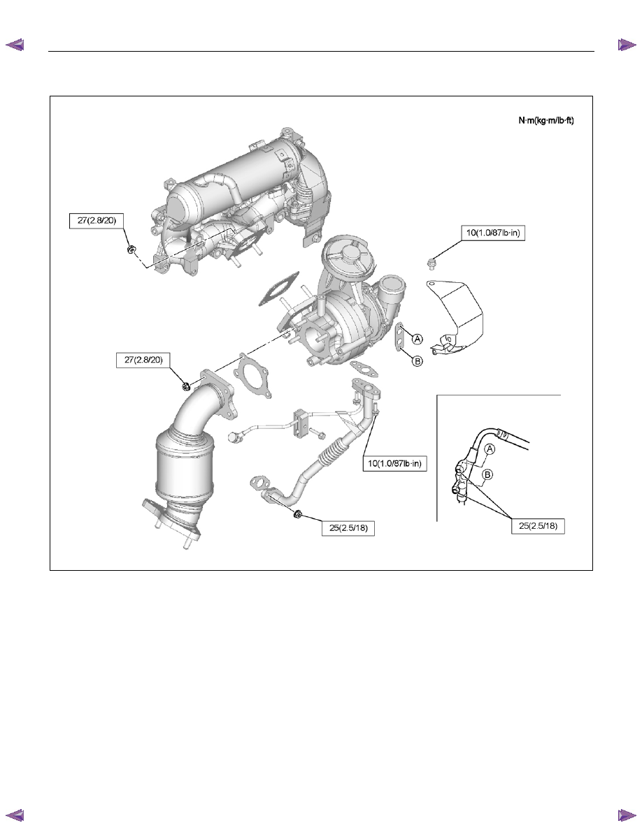
Installation
1. Install the gasket and the turbocharger to the
exhaust manifold. Temporarily tighten nuts.
2. Install the oil feed and return pipe and temporarily
tighten.
3. Tighten the turbocharger nuts to the specified
torque.
Tightening torque: 27 N
⋅⋅⋅⋅m (2.8 kg⋅⋅⋅⋅m / 20 lb ft)
4. Tighten the oil feed and return pipe bolts and nuts
to the specified torque.
Tightening torque (Turbocharger side):
10 N
⋅⋅⋅⋅m (1.0 kg⋅⋅⋅⋅m / 87 lb in)
Tightening torque (Crank case side):
25 N
⋅⋅⋅⋅m (2.5 kg⋅⋅⋅⋅m / 18 lb ft)
5. Install the water feed and return pipe to the
turbocharger.
Tightening torque: 25 N
⋅⋅⋅⋅m (2.5 kg⋅⋅⋅⋅m / 18 lb ft)
6. Install the heat protector to the turbocharger.
Tightening torque: 10 N
⋅⋅⋅⋅m (1.0 kg⋅⋅⋅⋅m / 18 lb ft)
7. Install the turbocharger bracket.
8. Install the catalyst converter.
Tighten the nuts to the specified torque.
Tightening torque: 27 N
⋅⋅⋅⋅m (2.8 kg⋅⋅⋅⋅m / 20 lb ft)
9. Install the mud cover of front RH fender skirt (4
×4
only).
10. Install the front exhaust pipe.
Tighten the nuts to the specified torque.
Tightening torque
Exhaust Manifold Side: 67 N
⋅⋅⋅⋅m (6.8 kg⋅⋅⋅⋅m / 49 lb ft)
Exhaust Pipe Side: 43 N
⋅⋅⋅⋅m (4.4 kg⋅⋅⋅⋅m / 32lb ft)
11. Install the intercooler.
• Install the intercooler.
• Install the two intake hoses.
• Connect the BARO sensor harness connector.
12.
Install the intake duct between the turbocharger
and the air cleaner.
Tightening torque: 6 N
⋅⋅⋅⋅m (0.6 kg⋅⋅⋅⋅m / 52 lb in)
13.Replenish the coolant.
ENGINE MECHANICAL (4JK1/4JJ1) 6A-45
Torque Specifications
RTW76ALF000501
6A-46 ENGINE MECHANICAL (4JK1/4JJ1)
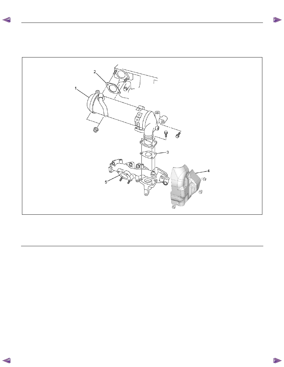
Exhaust Manifold (High Output)
Components
RTW76FMF000101
Legend
1. EGR
Cooler
2. EGR Cooler Gasket
3. EGR Cooler Gasket
5.
Heat
Protector
6. Exhaust
Manifold
ENGINE MECHANICAL (4JK1/4JJ1) 6A-47
Removal
1. Drain the engine coolant.
2. Remove the turbocharger.
• Refer to “Turbocharger”.
3. Remove the EGR cooler heat protector.
4. Disconnect the water hoses from the EGR cooler
water pipes.
5. Remove the EGR cooler.
6. Remove the exhaust manifold.
RTW76ASH002101
Inspection
• Inspection of the exhaust manifold. Inspect the
plane surface of the plane on which the
manifold and the cylinder head are to be
installed.
Manifold installation plane surface
mm (in)
Standard
0.3 (0.01) or lower
Limit 0.5
(0.02)
Caution:
If the plane surface exceeds the limit, replace it.
LNW21BSH022301
• Check a crack in the exhaust manifold visually.
Carefully inspect the turbocharger for abrasion and/or
excessive wear. Make any necessary adjustments,
repairs, and/or part replacements.
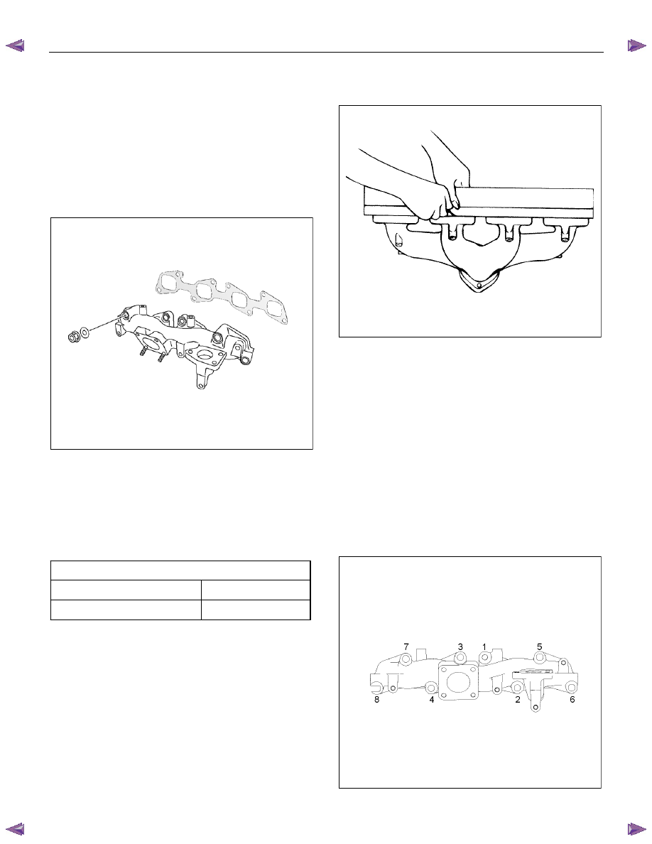
Installation
1. Put the gasket in to install the exhaust manifold.
• Tighten up with the 8 nuts according to the
order given in the illustration.
Tightening torque: 52 N
⋅⋅⋅⋅m (5.3 kg⋅⋅⋅⋅m / 38 lb ft)
Caution:
Do not tighten up too much because it hampers
expansion and contraction due to the heat from the
manifold.
RTW76ASH002201
Нет комментариевНе стесняйтесь поделиться с нами вашим ценным мнением.
Текст