Isuzu KB P190. Manual — part 245
6C – 16 FUEL SYSTEM
FILLER NECK
Removal
1. Remove the fuel tank.
NOTE: Refer to "Fuel Tank" in this section.
2. Put a marking the following point as the filler neck assembly
is restored.
• Each joint area of the hose (to restore axial direction and
insertion length of the hose)
• Each fasten area of the clamp (to restore axial direction
and position of the clamp)
• Each bolt in the clamp (to restore fasten length of bolt in
the clamp)
• The band clip (to restore position and fasten length of
the band clip)
NOTE: Cover end of each hose and pipe to prevent any dust
entering.
Installation
1. Align each marking and restore the following point.
• Each joint area of the hose (Restore axial direction and
insertion length of the hose)
• Each fasten area of the clamp (Restore axial direction
and position of the clamp)
• Each bolt in the clamp (Restore fasten length of bolt in
the clamp)
Torque
N·m (kg·m / lb ft)
2.5 (0.25 / 21.7)
filler neck side except flat deck model.
• The band clip (Restore position and fasten length of the
band clip)
2. Install the fuel tank.
NOTE: Refer to "Fuel Tank" in this section.
FUEL SYSTEM 6C – 17
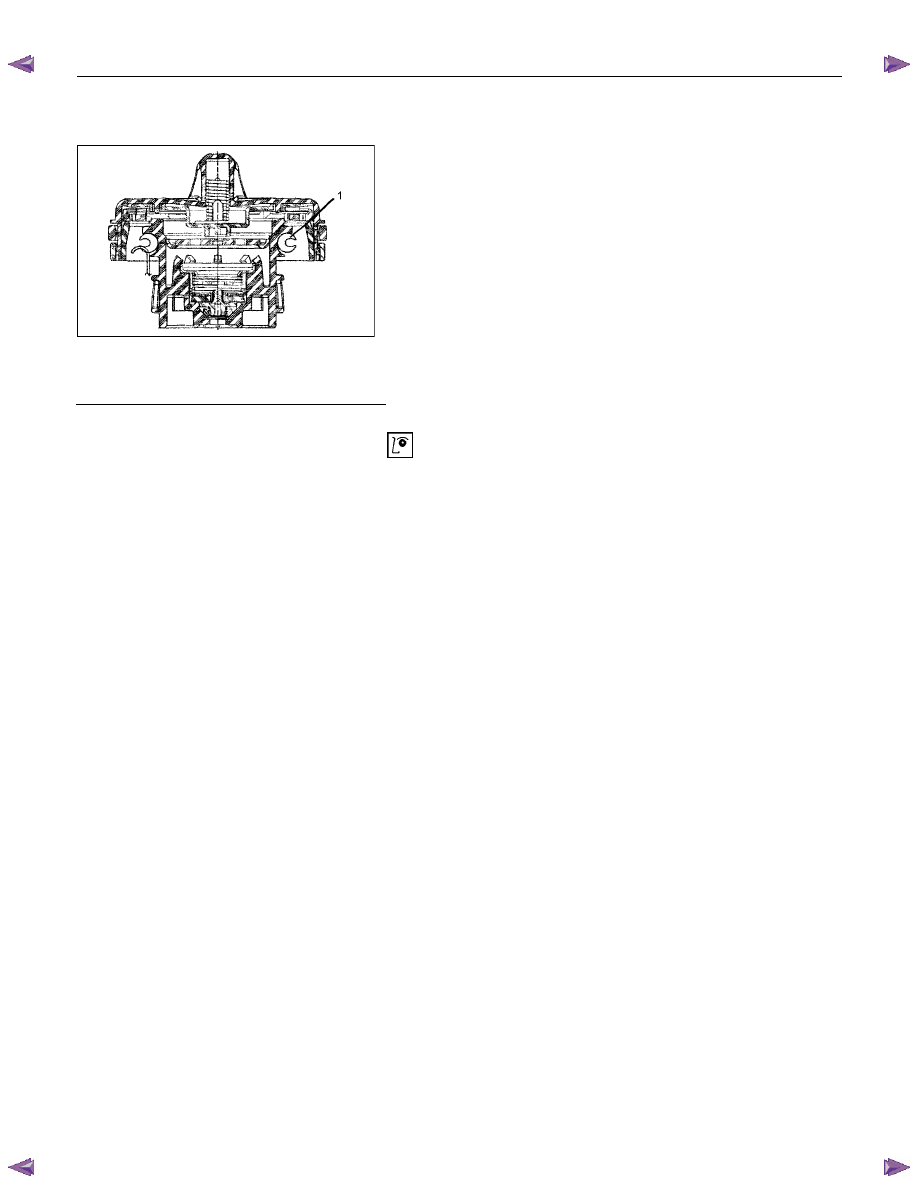
FUEL FILLER CAP
RTW46CSH000301
Legend
1. Seal Ring
General Description
A vacuum valve and pressure valve are built into the fuel filler
cap which adjusts the fuel pressure in the fuel tank to prevent
fuel tank damage.
Inspection
The fuel filler cap must be inspected for seal condition.
The fuel filler cap must be replaced if found defective
CAUTION: A replacement fuel filler cap must be the same
as the original. The fuel filler cap valve was designed
primarily for this application and must be replaced with
the same type or decreased engine performance may
occur.
6C – 18 FUEL SYSTEM
INJECTION PUMP
REMOVAL AND INSTALLATION
Read this Section carefully before performing any removal and installation procedure. This Section gives you
important points as well as the order of operation. Be sure that you understand everything in this Section before you
begin.
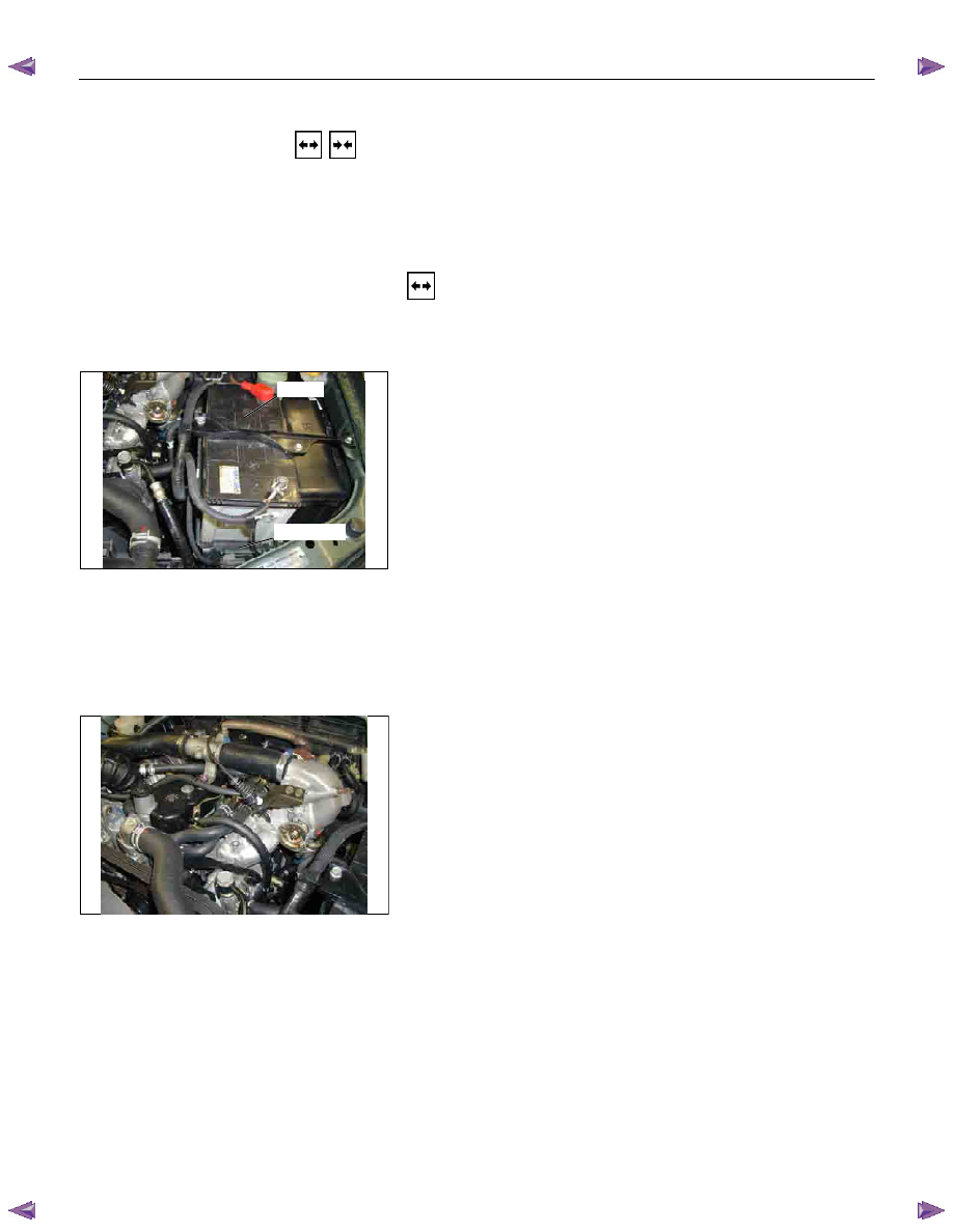
Removal
1. Battery
Remove the battery from the battery tray.
Battery
Battery tray
P1010011
2. Drive Belt
1) Loosen the adjust bolt of the power steering pump
pulley.
2) Remove the drive belt.
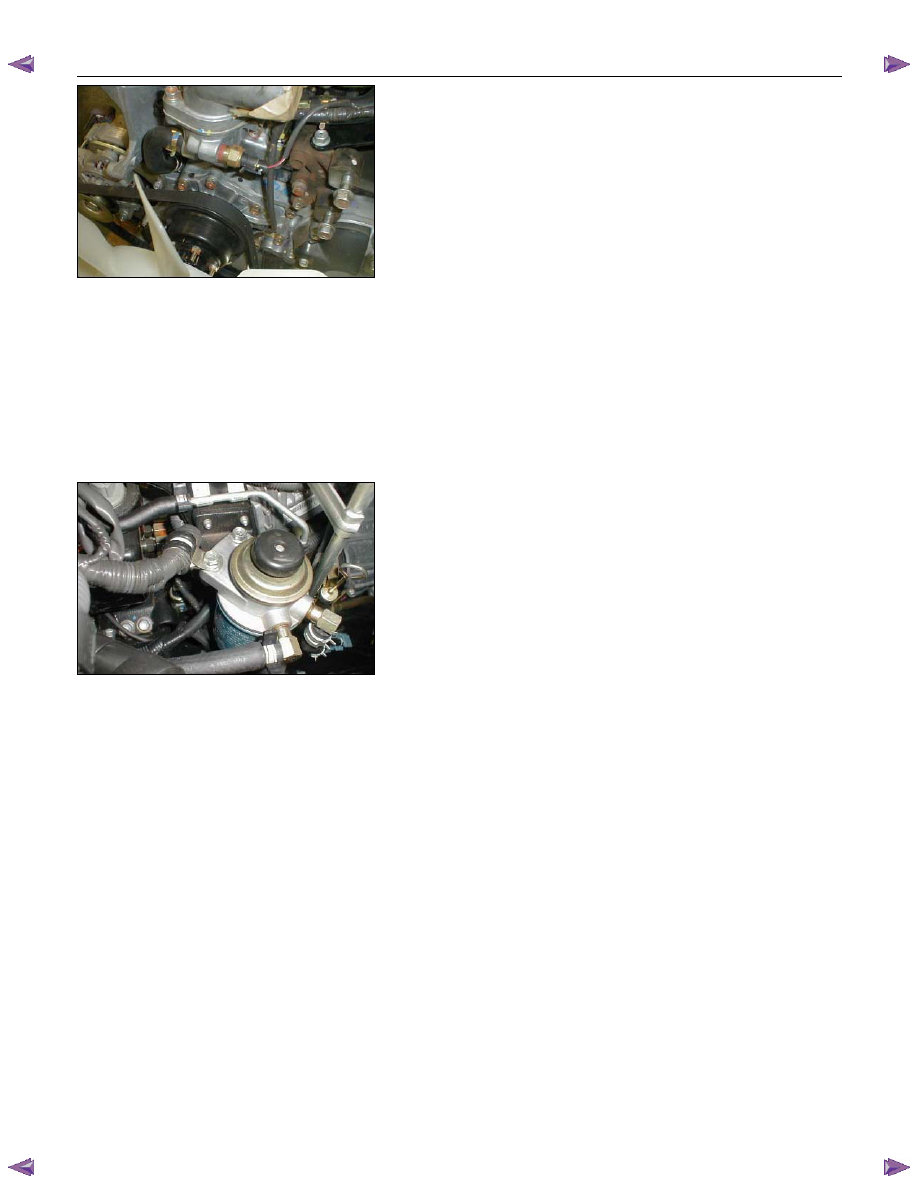
3. Power Steering Pump Assembly
P1010003
4. Accelerator Control Cable
Disconnect the accelerator cable from the intake throttle.
5. Vacuum Hose
Disconnect the vacuum hose from the EGR valve and the
intake throttle.
6. Fan
FUEL SYSTEM 6C – 19
7. Power Steering Pump Bracket
6C-4
8.
Throttle Position Sensor Harness Connector
(4JA1TC/4JH1TC only)
Disconnect the harness connector from the throttle
position sensor.
9. Oil Level Gauge
10. Fuel Pipe
1) Disconnect the fuel hoses from the fuel filter or priming
pump.
2) Disconnect the fuel hoses from the injection pump.
11. Fuel Filter Assembly (Except EURO III model)
6C-5
12. Fuel Filter Bracket (Except EURO III model)
13. Leak Off Hose
Disconnect the leak off hose at the injection pump.
14. Injection Pipe Clip
15. Injection Pipe
1) Loosen the injection pipe sleeve nuts at the delivery
valve side and the injection nozzle side.
Note:
Do not apply excessive force to the injection pipes.
2) Loosen the injection pipe clip.
3) Remove the injection pipes.
Note:
Plug the delivery holder ports with the caps to prevent
the entry of foreign material.
16. Intake Manifold
1) Remove the EGR valve from the intake manifold and
EGR pipe.
2) Loosen the intake rubber hoses clip.
3) Loosen the intake manifold bolts and nuts.
17. Injection Pump Cover (4JA1TC/4JH1TC only)
Нет комментариевНе стесняйтесь поделиться с нами вашим ценным мнением.
Текст