Isuzu KB P190. Manual — part 246
6C – 20 FUEL SYSTEM
020L200017
RTW46CSH000201
18. Timing Check Hole Cover
1) Remove the timing check hole cover.
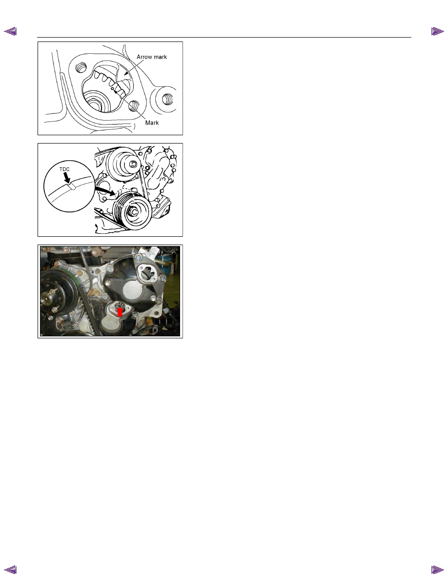
2) For ease in reinstalling the injection pump, align the
timing mark on the timing gear case cover by turning
the crankshaft using wrench.
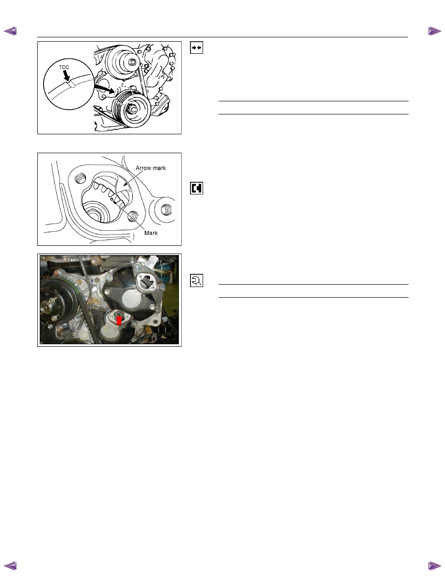
And bring the piston in the No.1 cylinder to TDC on the
compression stroke by turning the crankshaft until the
crankshaft pulley TDC line aligned with the timing
mark.
Note:
If the check hole cover is reinstalled with the lock bolt
still in place, the crank pulley will not turn.
6C-7
3) Insert the lock bolt (M6 x 30) into the scissors gear idle
gear “B” fixing hole to prevent the scissors gear from
turning.
29. Injection Pump Bracket
20. Injection Pump
FUEL SYSTEM 6C – 21
RTW46CSH000201
Installation
1. Injection Pump
1) Install the injection pump gear (When gear is
removed).
Injection Pump Gear Nut
N
⋅m (kg⋅m/lb ft)
64 (6.5 / 47)
2) Bring the piston in the No.1 cylinder to TDC on the
compression stroke by turning the crankshaft until the
crankshaft pulley TDC line aligned with the timing
mark.
020L200017
3) Install the injection pump to the timing gear case with
align the timing mark on the pump gear to the arrow
mark on the timing gear case cover.
4) Check that the setting marks of the injection pump
gear and the idler gear B are aligned.
5) Remove the lock bolt (M6
× 30) from the idle gear “B”.
6C-7
6) Tighten the injection pump fixing bolts to the specified
torque.
Injection Pump Bolts Torque
N·m (kg·m/lb ft)
19 (1.9 / 14)
6C – 22 FUEL SYSTEM
4JA1T (L)
RTW46CSH000101
4JA1TC/4JH1TC
RTW36AMH000101
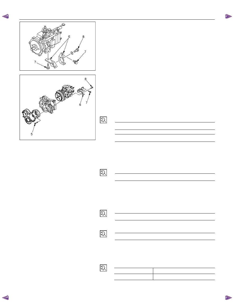
2. Injection Pump Bracket
1) Install the injection pump bracket (6) and the bracket
bolts (7) and (8) to the cylinder body. Temporarily
tighten the bracket bolts.
2) Tighten the bracket bolts (7) to the specified torque.
3) Tighten the bracket bolts (8) to the specified torque.
Note:
Tighten the bracket bolt (8) first.
Injection Pump Bracket Torque
N·m(kg·m / lb ft)
(8) 19 (1.9 / 14)
(7) 40 (4.1 / 30)
3. Timing Check Hole Cover
Install the timing check hole cover and tighten bolts to the
specified torque.
Timing Check Hole Cover Bolts
Torque
N·m(kg·m / lb ft)
8 (0.8 / 69)
4. Injection Pump Cover (4JA1TC/4JH1TC only)
5. Intake
Manifold
1) Install the intake manifold with gasket.
Intake Manifold Bolts
Torque
N·m(kg·m / lb ft)
19 (1.9 / 14)
Intake Manifold Nuts Torque
N·m(kg·m / lb ft)
24 (2.4 / 17)
2) Install the EGR valve to the intake manifold and EGR
pipe temporarily.
3) Tighten the nuts and bolts to the specified torque
Torque N
⋅m (kg⋅m/lb ft)
Nuts 24
(2.4/17)
Bolts 27
(2.8/20)
FUEL SYSTEM 6C – 23
6. Injection
Pipe
Install the injection pipe.
Injection Pipe Torque
N·m(kg·m / lb ft)
29 (3.0 / 22)
Nozzle Side (4JA1TC/4JH1TC)
N·m(kg·m / lb ft)
29 (3.0 / 22)
Pump Side (4JA1TC/4JH1TC)
N·m(kg·m / lb ft)
40 (4.1 / 30)
7. Injection Pipe Clip
Install the injection pipe clip.
Note:
Make absolutely sure that the clip is correctly
positioned.
Injection Pipe Clip Torque
N·m(kg·m / lb in)
8 (0.8 / 69)
8. Leak Off Pipe and Leak Off Hose
Install the leak off pipe to injection nozzle and connect the
leak off hose to the injection pump.
9. Fuel Filter Bracket (Except EURO III model)
Install the fuel filter bracket and tighten bolts to the
specified torque.
Fuel Filter Bracket Bolts Torque
N·m(kg·m / lb ft)
21 (2.1 / 15)
10. Fuel Filter Assembly (Except EURO III model)
Install the fuel filter assembly to bracket and tighten bolts
to the specified torque.
Fuel Filter Assembly Bolts
Torque
N·m(kg·m / lb ft)
21 (2.1 / 15)
11. Fuel Pipe
1) Connect the fuel hoses to the fuel filter or priming
pump.
2) Connect the fuel hoses to the injection pump.
12. Oil Level Gauge
Install the oil level gauge and tighten bolts to the specified
torque.
Oil Level Gauge Bolts
Torque
N·m(kg·m / lb ft)
M8: 19 (1.9 / 14)
M6: 8 (0.8/6 lb in)
Нет комментариевНе стесняйтесь поделиться с нами вашим ценным мнением.
Текст