Isuzu KB P190. Manual — part 985

Automatic Transmission – 4L60E – On-vehicle Servicing
Page 7C4–27
To prevent personal injury, wear safety
glasses when removing the clip.
N O T E
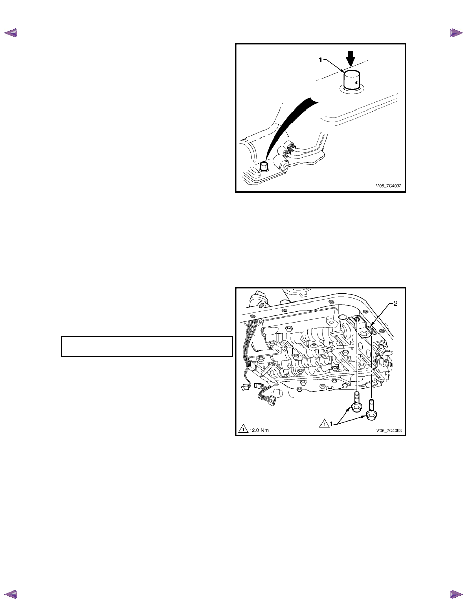
Note the following when removing the solenoid:
• If required, rotate the solenoid until the flat
part of the clip becomes visible.
• The removal is only necessary to access the
TCC solenoid attaching bolts.
4
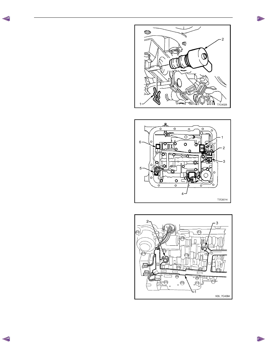
Using a hooked piece of wire or a small flat blade
screwdriver, remove the clip (1) retaining the
TCC PWM solenoid (2).
5
With a twisting and pulling motion remove the
TCC PWM solenoid from the control valve body,
remove and discard the O-ring.
Figure 7C4 – 29
6
Remove the two bolts (1) attaching the TCC solenoid
assembly (2) to the control valve body.
Figure 7C4 – 30
7
Withdraw the TCC solenoid assembly (1) from the
control valve body (oil pump housing), remove and
discard the O-ring.
8
Lower the harness (2) and TCC solenoid, allow it to
hang from the pass-thru connector (3).
9
Remove the control valve body, refer to
3.14
Control Valve Body.
N O T E
This is necessary to provide clearance for the
pass-thru connector to be removed.
Figure 7C4 – 31
Automatic Transmission – 4L60E – On-vehicle Servicing
Page 7C4–28
10
Lower the transmission to provide clearance between
the floor pan and the pass-thru connector located at
the right-hand rear of the transmission case.
11
Install the connector release, Tool No. 700-4208 (1)
over the pass-thru connector and use hand force to
push the tool down compressing the four retaining
tangs on the connector.
12
Pull the pass-thru connector free from the
transmission case and remove the control valve body
harness and TCC solenoid assembly from the
transmission.
13
Remove the O-ring from the pass-thru connector and
discard.
Figure 7C4 – 32
Reinstall
1
Lubricate a new O-ring with petroleum jelly and fit it to the pass-thru connector.
2
Reinstall the pass-thru connector up through the hole in the transmission case pushing it in until all four retaining
tangs have emerged on the outside of the transmission case. Gently pull on the connector to check if engagement
is secured.
3
Reinstall the control valve body, refer to 3.14
Control Valve Body.
4
Lubricate a new O-ring with petroleum jelly and fit it to
the TCC solenoid (2).
5
Reinstall the TCC solenoid assembly in the control
valve body , tighten the two attaching bolts (1) to the
correct torque specification.
TCC solenoid attaching bolt
torque specification . . . . . . . . . . . 12.0 Nm
Figure 7C4 – 33
Automatic Transmission – 4L60E – On-vehicle Servicing
Page 7C4–29
6
Lubricate a new O-ring with petroleum jelly and fit it to
the TCC PWM solenoid (2).
7
Reinstall the TCC PWM solenoid in the control valve
body and secure it with the retaining clip (1).
Figure 7C4 – 34
8
Reconnect the control valve body harness connectors.
Connectors identification:
•
Transmission Fluid Pressure (TFP) Manual
Valve Position Switch (1)
•
1 – 2 Shift Valve Solenoid A (2)
•
2 – 3 Shift Valve Solenoid B (3)
•
Pressure Control Solenoid (PCS) (4)
•
Torque Converter Clutch Pulse Width Modulated
(TCC PWM) Solenoid (5)
•
3 – 2 Control Solenoid (6).
Figure 7C4 – 35
9
Secure the harness frame to the control valve body,
place the tab between the valve body and pressure
switch in location (1) and press the harness frame in
position on bolt bosses (2 and 3).
Figure 7C4 – 36
10
Reinstall the oil pan and filter and fill the transmission with the recommended automatic transmission fluid, refer to
3.1 Fluid Change and Filter Replacement.
11
Lower vehicle to the ground.
Automatic Transmission – 4L60E – On-vehicle Servicing
Page 7C4–30
12
Road test until the transmission has reached operating temperature. Re-check the fluid level and for any fluid leaks
from the oil pan area, refer to 2.1
Transmission Fluid.
3.14 Control Valve Body
Remove
1
Partially remove the control valve body harness until it hangs from the pass-thru connector, refer to
3.13
Control Valve Body Harness.
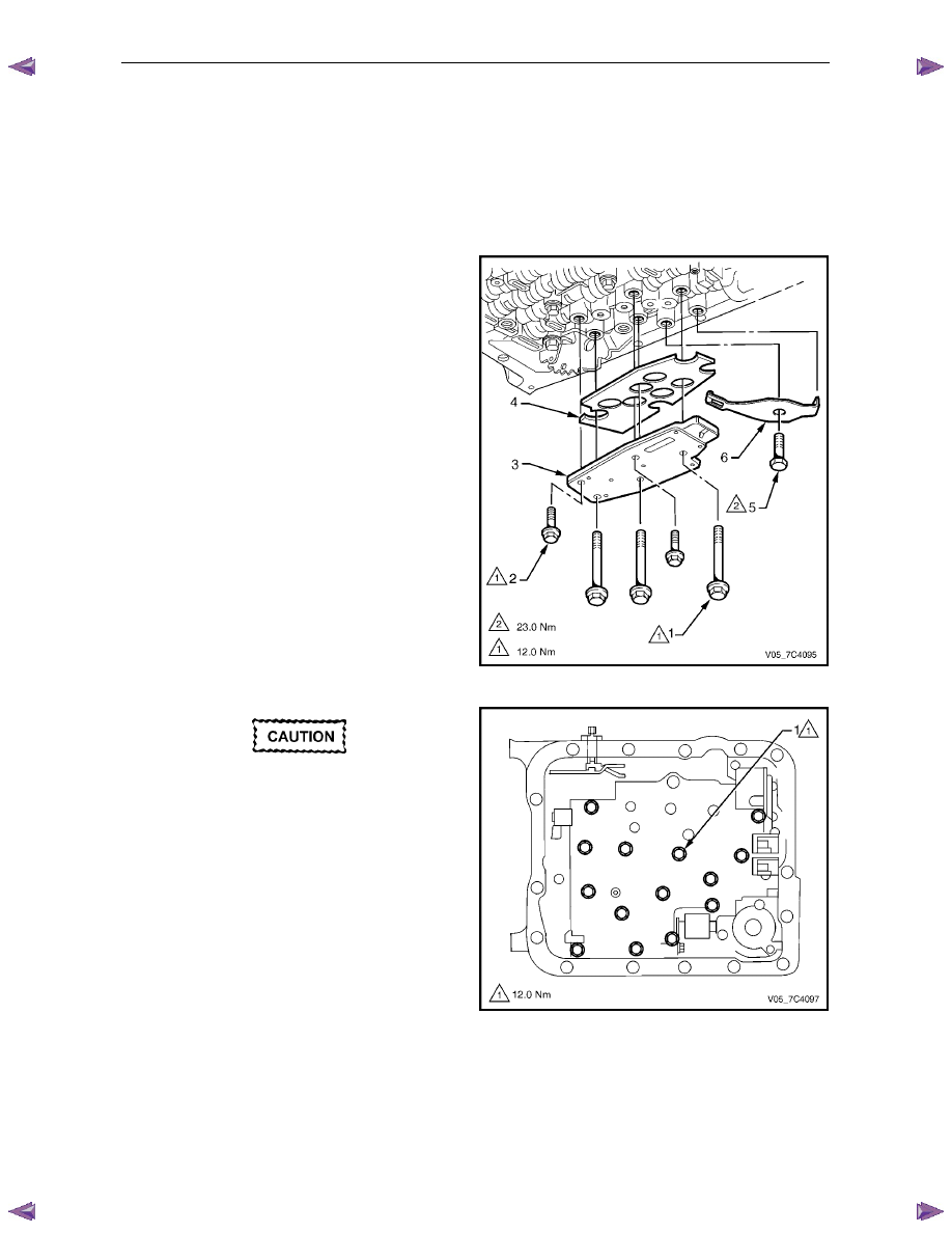
2
Remove the three long bolts (1) and the two short
bolts (2) attaching the transmission fluid pressure
(TFP) manual valve position switch assembly (3),
remove the switch and discard the shield (4).
3
Remove the attaching bolt (5) and the manual detent
spring (6).
Figure 7C4 – 37
In the following procedure support the
control valve body before removing the last
bolt.
N O T E
The removal may be more manageable by
removing the bolts in a spiral pattern starting
from the outside, removing the centre bolt last.
4
Remove the fourteen remaining bolts (1) attaching the
control valve body.
Figure 7C4 – 38
Нет комментариевНе стесняйтесь поделиться с нами вашим ценным мнением.
Текст