Isuzu KB P190. Manual — part 984

Automatic Transmission – 4L60E – On-vehicle Servicing
Page 7C4–23
3
Remove the bolt (1), six places, attaching the
extension housing (2) to the transmission case.
4
Remove the extension housing and seal (3) from the
rear of the transmission case, discard the seal.
Figure 7C4 – 22
Take care not to scratch the machined seal
recess in the extension housing as
transmission fluid may weep past the outer
diameter of the installed seal.
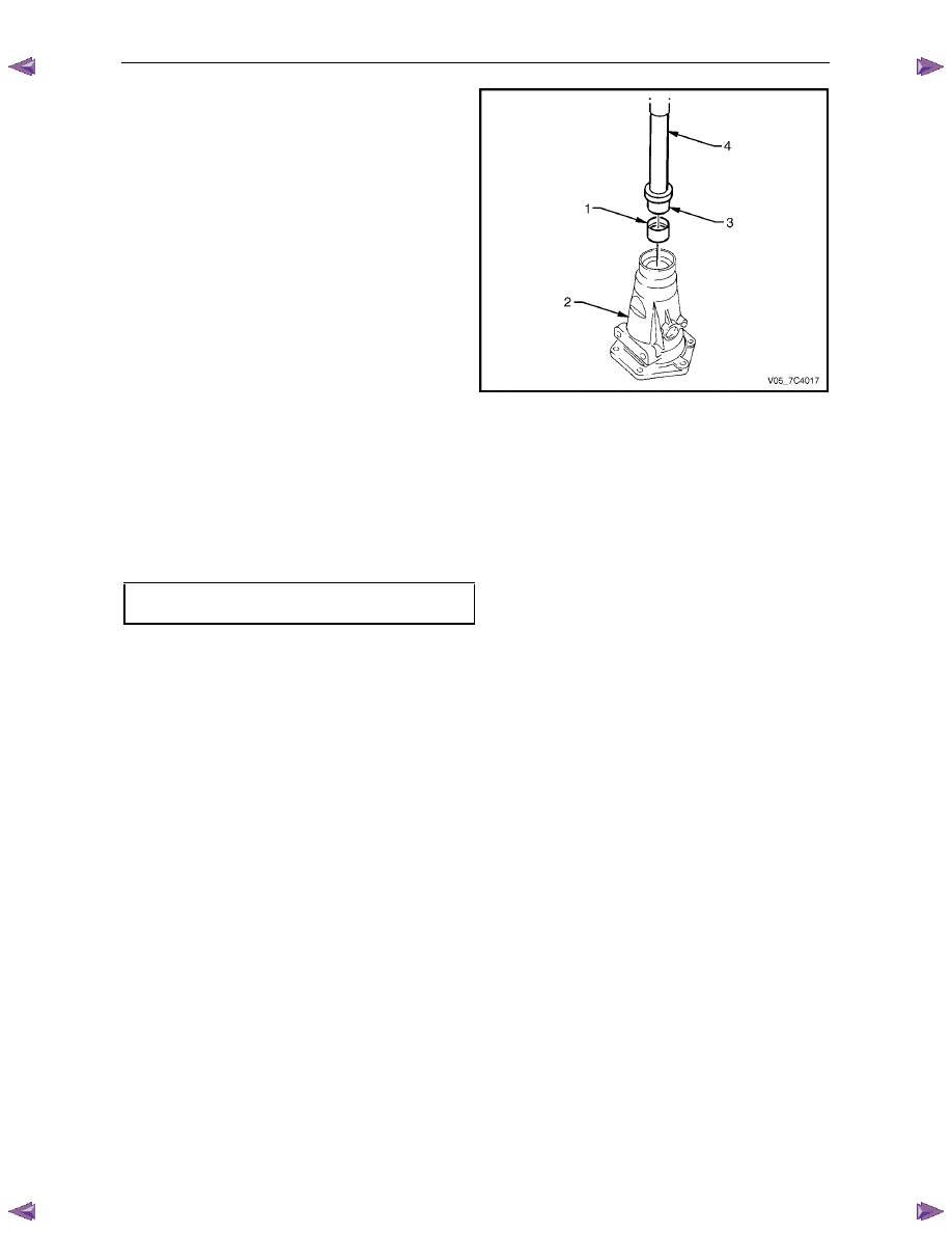
5
If the extension housing rear bush is to be replaced,
remove the oil seal (1) from the extension housing (2),
using a suitable removing tool such as Tool No. E308
and discard the seal.
Figure 7C4 – 23
N O T E
Before removal, take note of the orientation of
the split in the bush to assist in the replacement
process.
6
If required, using the bush remover, Tool
No. J23062-14 (1) and driver handle, Tool
No. J8092 (2), press the bush (3) out of the extension
housing (4) and discard.
Figure 7C4 – 24
Automatic Transmission – 4L60E – On-vehicle Servicing
Page 7C4–24
7
Lubricate the outside of a new bush with automatic
transmission fluid to reduce the chance of material
pick-up.
8
Ensure the split in the new bush (1) is in the same
orientation as noted previously and Install it into the
extension housing (2) using the installer tool, Tool
No. J34196-4 (3) and driver handle, Tool
No. J8092 (4).
Figure 7C4 – 25
Reinstall
Installation of the extension housing is the reverse of the removal procedure, noting the following:
1
If required, install a new oil seal in the extension housing, refer to 3.8
Extension Housing Oil Seal.
2
Lubricate a new seal with clean automatic transmission fluid and fit to the extension housing mounting flange.
3
Tighten the six bolts attaching the extension housing to the correct torque specification.
Extension housing attaching bolt
torque specification . . . . . . . . . 42.0 – 48.0 Nm
3.10 Adaptor Housing, 4WD
Remove and Reinstall
For service operation of the transmission adaptor housing for 4WD vehicles, refer to 7D Transfer Case and Adaptor
Housing.
Automatic Transmission – 4L60E – On-vehicle Servicing
Page 7C4–25
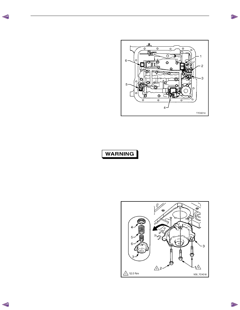
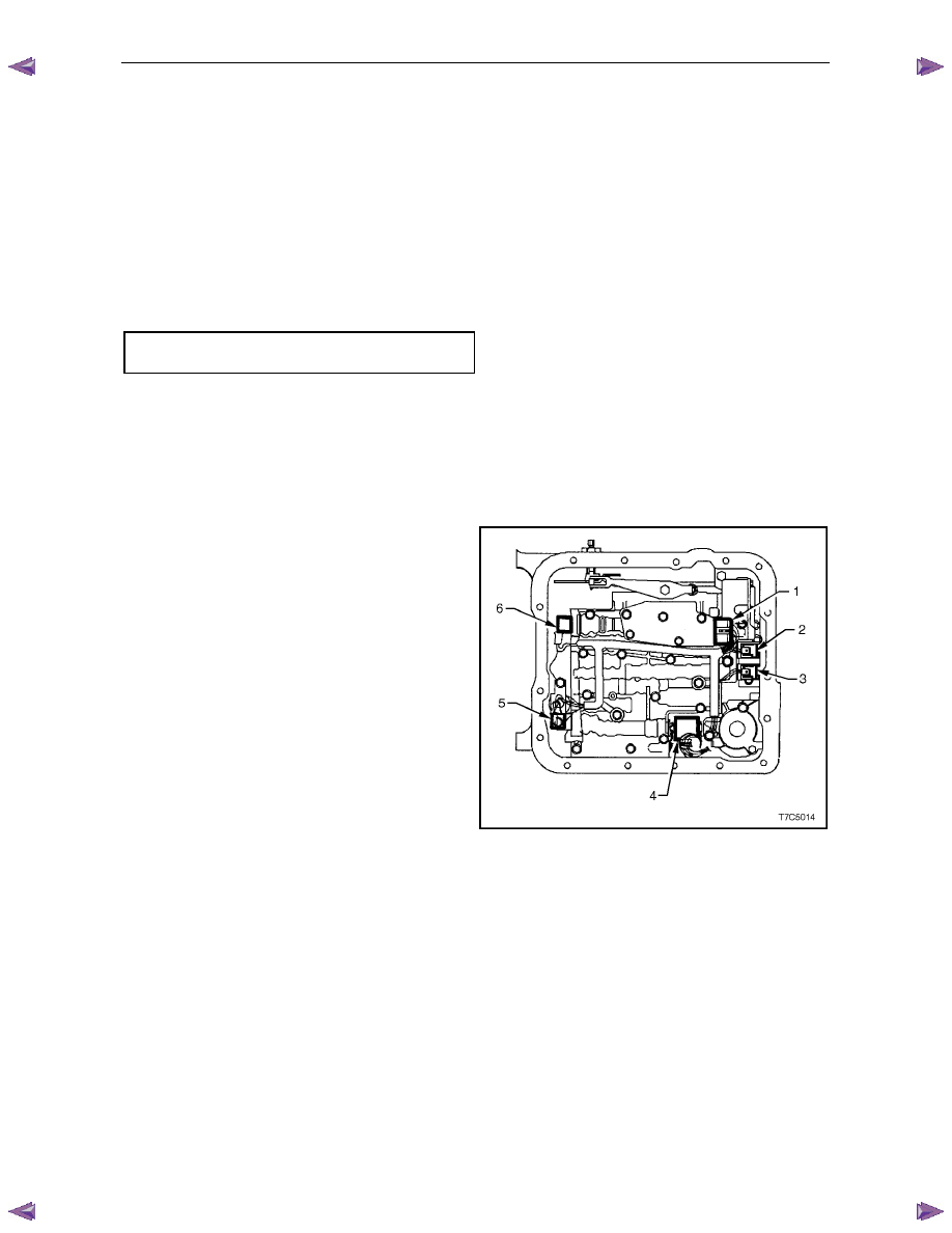
3.11 Shift Solenoid Locations
Location and Identification
Legend
1
Transmission Fluid Pressure (TFP) Manual
Valve Position Switch.
2
1 – 2 Shift Valve Solenoid A.
3
2 – 3 Shift Valve Solenoid B.
4
Pressure Control Solenoid (PCS).
5
Torque Converter Clutch Pulse Width Modulated
(TCC PWM) Solenoid.
6
3 – 2 Control Solenoid.
Figure 7C4 – 26
To service the TCC PWM solenoid, refer to 3.13
Control Valve Body Harness.
3.12 1 – 2 Accumulator Assembly
Throughout this Section when using
compressed air and cleaning fluids, wear
safety glasses and gloves to avoid personal
injury.
Remove
1
Remove the oil pan and filter, refer to 3.1
Fluid Change and Filter Replacement.
2
Remove the two short bolts (1) and one long bolt (2)
attaching the accumulator cover (3) and remove the
cover.
3
Using low pressure compressed air applied to the
drilling in the cover, remove the 1 – 2 accumulator
piston and seal assembly (4) and the two
springs (5 and 6).
4
Remove the seal from the piston and discard the seal.
Figure 7C4 – 27
Automatic Transmission – 4L60E – On-vehicle Servicing
Page 7C4–26
Clean and Inspect
1
Clean all components in a commercially available cleaning fluid and blow dry using compressed air.
2
Inspect the springs and ensure they are not distorted or broken, replace as required.
3
Inspect all machined surfaces for damage, wear or burrs.
Reinstall
Reinstallation of the 1 – 2 accumulator assembly is the reverse of the removal procedure, noting the following:
1
Lubricate a new seal with petroleum jelly and install it to the piston. Ensure the piston seal does not bind in the
piston groove.
2
Tighten the three bolts attaching the accumulator cover to the correct torque specification.
1 – 2 Accumulator cover attaching
bolt torque specification . . . . . . . . . .12.0 Nm
3.13 Control Valve Body Harness
Remove
1
Raise the vehicle and support in a safe manner, refer to 0A General Information for the location of support points.
2
As required, remove the oil pan and filter, refer to 3.1
Fluid Change and Filter Replacement.
3
Disconnect the control valve body harness connectors
from all electrical components except the torque
converter clutch (TCC) solenoid, which is hard wired.
Connectors identification:
•
Transmission Fluid Pressure (TFP) Manual
Valve Position Switch (1)
•
1 – 2 Shift Valve Solenoid A (2)
•
2 – 3 Shift Valve Solenoid B (3)
•
Pressure Control Solenoid (PCS) (4)
•
Torque Converter Clutch Pulse Width Modulated
(TCC PWM) Solenoid (5)
•
3 – 2 Control Solenoid (6).
Figure 7C4 – 28
Нет комментариевНе стесняйтесь поделиться с нами вашим ценным мнением.
Текст