Isuzu KB P190. Manual — part 231

ENGINE MECHANICAL 6A – 119
Installation
1. Exhaust Manifold
1) Install the exhaust manifold to the cylinder head with
the manifold gasket.
2) Tighten the exhaust manifold bolts and nuts to the
specified torque a little at a time.
Exhaust Manifold Bolt and Nuts
Torque N·m(kg·m/Ib
ft)
24 (2.4/17)
3) Install the exhaust manifold bracket to the manifold
and the cylinder body.
Manifold Bracket Bolt Torque
N·m(kg·m/Ib ft)
19 (1.9/14)
RTW46ASH001301
2. Oil Cooler with Oil Filter
1) Install the O-ring to the oil filter body flange groove.
2) Install the oil filter body to cylinder block and tighten to
the specified torque.
Oil Filter Body Bolt and Nut
Torque N·m(kg·m/Ib
ft)
BOLT 19 (1.9/14)
NUT 24 (2.4/17)
3. Generator Bracket
Install the generator bracket to the cylinder body and
tighten the bracket bolts to the specified torque.
Bracket Bolt Torque
N·m(kg·m/Ib ft)
40 (4.1/30)
027R100003
027R100004
066RY00001
6A – 120 ENGINE MECHANICAL
4. Water Inlet Pipe
1) Tighten the water inlet pipe bolts to the specified
torque.
Suction Pipe Bolt Torque
N·m(kg·m/Ib ft)
19 (1.9/14)
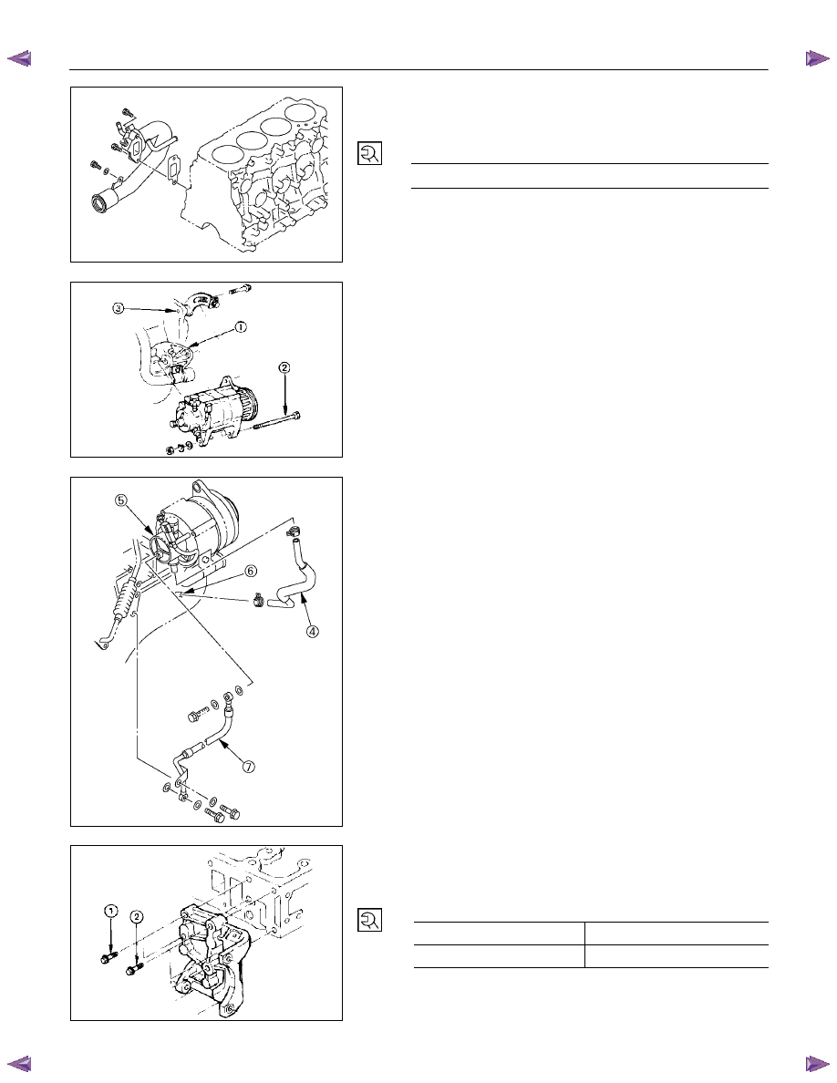
5. Generator and Adjusting Plate
1) Install the generator to the bracket (1).
2) Temporarily tighten the generator bolt (2) and
adjusting plate bolts (3).
The bolts will be finally tightened after installation of
the cooling fan drive belt.
3) Connect the vacuum pump rubber hose (4) to the
vacuum pump (5), and the oil pan (6).
6. Vacuum Pump Oil Return Hose
Connect the vacuum oil pipe (7) to the vacuum pump, and
the cylinder body
052R300001
7. Compressor Bracket
1) Install the compressor bracket to the cylinder head.
2) Tighten the bracket bolts to the specified torque.
Bracket Bolt Torque
N·m(kg·m/Ib ft)
M8×1.25
19 (1.9/14)
M10×1.25
40 (4.1/30)
066RY00002
032R300001
042RY00003
ENGINE MECHANICAL 6A – 121
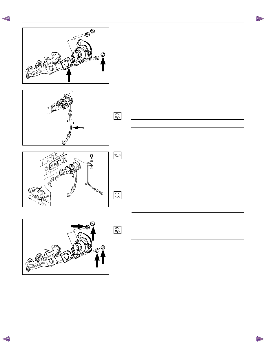
8. Turbocharger
1) Install the turbocharger and the gasket.
2) Temporarily tighten the turbocharger nuts at this time.
They will be fully tightened after the installation of the
turbocharger oil pipe.
Always install new nuts and new gasket.
3) Install the oil return pipe with gasket to the
turbocharger.
4) Tighten the turbocharger oil return pipe to the
specified torque.
Bracket Bolt Torque
N·m(kg·m/Ib ft)
8 (0.8/6)
5) Before installing the oil feed pipe, supply 10 - 20 cc of
clean engine oil to the turbocharger center housing
through the oil feed opening.
6) Turn the rotating assembly with your hand to
thoroughly lubricate the internal parts.
7) Tighten the oil feed pipe to the specified torque.
Turbocharger Oil Feed Pipe Joint
Bolt Torque
N·m(kg·m/Ib ft)
M10×1.5
22 (2.25/16)
M14×1.5
54 (5.5/40)
RTW46ASH001501
8) Tighten the turbocharger nut to the specified torque.
Turbocharger Nut Torque
N·m(kg·m/Ib ft)
27 (2.7/20)
036R100001
027R100005
027R100002
6A – 122 ENGINE MECHANICAL
RTW46ASH001601
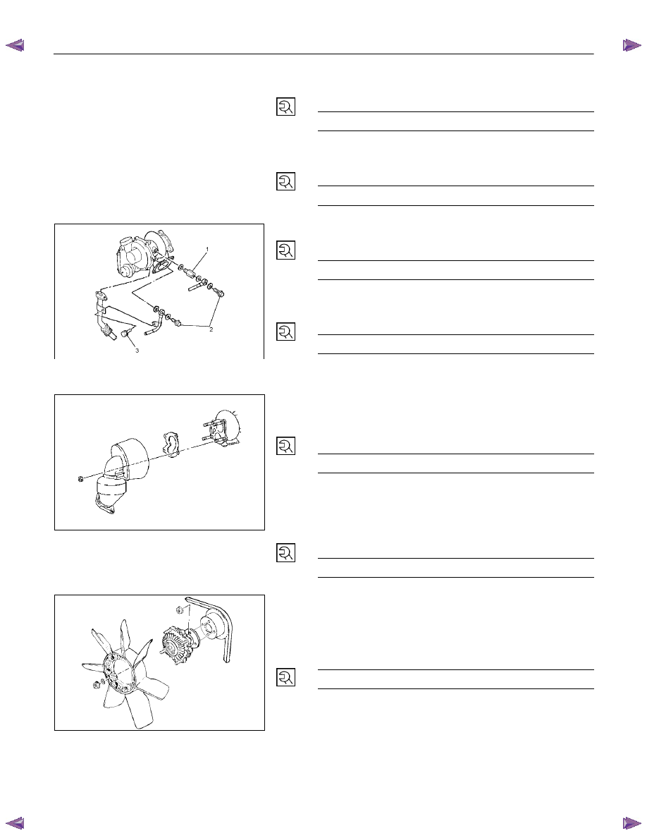
9) Install the water feed adapter (1) with the gaskets to
turbocharger and tighten to the specified torque.
Adapter Torque
N·m(kg·m/Ib ft)
39 (4.0/29)
10) Install the water feed pipe with the gaskets and tighten
to the specified torque.
Water Return Pipe Torque
N·m(kg·m/Ib ft)
39 (4.0/29)
11) Install the water return pipe with the gaskets and
tighten to the specified torque.
Water Return Torque
N·m(kg·m/Ib ft)
39 (4.0/29)
12) Clamp the water feed pipe to the oil return pipe of the
turbocharger.
Fixing Bolt (3) Torque
N·m(kg·m/Ib ft)
8 (0.8/6)
13) Install the hoses for the water feed and return.
9. Catalytic Converter
Install the catalytic converter with gasket and tighten the
nut to the specified torque.
Catalytic converter Nut Torque
N·m(kg·m/Ib ft)
27 (2.7/20)
Do not install the catalytic converter, if drop down it.
10. Heat Protector
Install the heat protector and tighten the bolt to the
specified torque.
Heat Protector Bolt Torque
N·m(kg·m/Ib ft)
9 (0.9/6.5 Ib in)
033R300002
11. Cooling Fan Pulley
1) Install the cooling fan pulley to the water pump.
2) Tighten the cooling fan pulley nuts to the specified
torque.
Pulley Nut Torque
N·m(kg·m/Ib ft)
8 (0.8/6)
12. Oil Cooler Water Pipe
13. Fuel Leak Off Pipe
14. Oil Pressure Warning Switch
027R100007
Нет комментариевНе стесняйтесь поделиться с нами вашим ценным мнением.
Текст