Freightliner Business Class. Manual — part 24
U-Bolt Torque Values
Description
Size
Torque
lbf·ft (N·m)
Spring Assembly U-Bolt High Nuts
5/8–18
Stage 1: Hand Tighten
Stage 2: 60 (81)
*
Stage 3: 200 (271)
*
Stage 4: 180 to 230 (245 to 313)
*
3/4–16
Stage 1: Hand Tighten
Stage 2: 60 (81)
*
Stage 3: 200 (271)
*
Stage 4: 270 to 330 (367 to 449)
*
7/8–14
Stage 1: Hand Tighten
Stage 2: 60 (81)
*
Stage 3: 200 (271)
*
Stage 4: 420 to 500 (571 to 680)
*
1–14
Stage 1: Hand tighten
Stage 2: 60 (81)
*
Stage 3: 200 (271)
*
Stage 4: 520 to 600 (707 to 816)
*
*
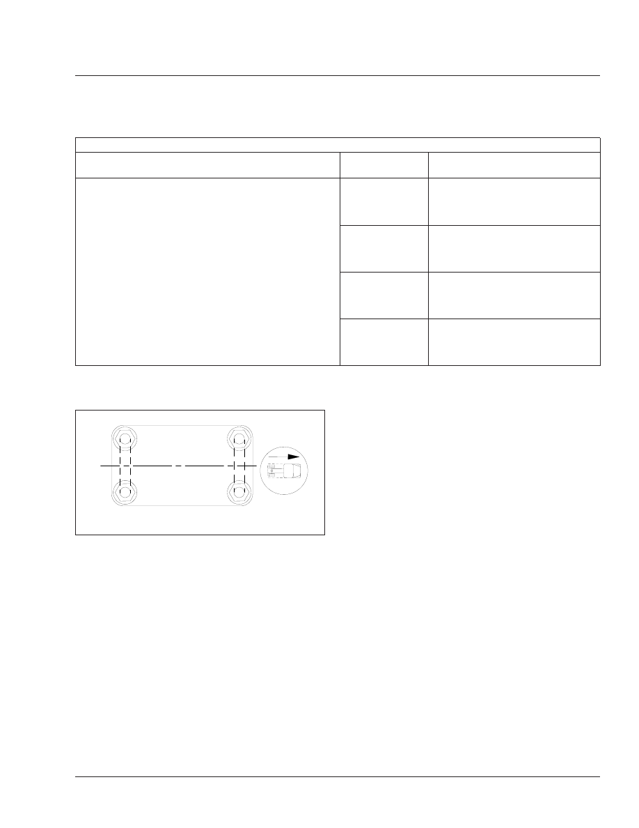
Tighten in a diagonal pattern as shown in
Table 1, U-Bolt Torque Values
01/05/99
f320783
1
2
3
4
Fig. 12, Tightening Pattern for U-Bolt High Nuts
Suspension
32
Business Class Trucks Maintenance Manual, July 1999
32/9
Title of Maintenance Operation (MOP)
MOP Number
All-Axle Alignment Checking . . . . . . . . . . . . . . . . . . . . . . . . . . . . . . . . . . . . . . . . . . . . . . . . . . . . . . . . . . 33–04
All-Wheel-Drive Front Axle Oil Changing . . . . . . . . . . . . . . . . . . . . . . . . . . . . . . . . . . . . . . . . . . . . . . . . . 33–06
All-Wheel-Drive Front Axle Oil Level Checking. . . . . . . . . . . . . . . . . . . . . . . . . . . . . . . . . . . . . . . . . . . . . 33–05
Knuckle Pin Lubricating . . . . . . . . . . . . . . . . . . . . . . . . . . . . . . . . . . . . . . . . . . . . . . . . . . . . . . . . . . . . . 33–01
Tie-Rod End Inspecting . . . . . . . . . . . . . . . . . . . . . . . . . . . . . . . . . . . . . . . . . . . . . . . . . . . . . . . . . . . . . 33–02
Tie-Rod End Lubricating . . . . . . . . . . . . . . . . . . . . . . . . . . . . . . . . . . . . . . . . . . . . . . . . . . . . . . . . . . . . . 33–03
Front Axle
33
Index, Alphabetical
Business Class Trucks Maintenance Manual, June 2001
33–01 Knuckle Pin Lubricating
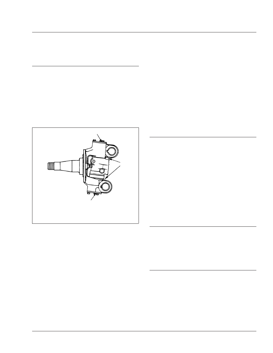
Hold a pressure gun on each fitting until fresh grease
appears. See
. This will ensure that all the old
contaminated grease has been forced out. It is not
necessary to exceed 4000 psi (27 560 kPa). The
best distribution of new lubricant and the best purg-
ing of old lubricant occurs when about 4000 psi (27
560 kPa) pressure is applied at the grease gun
nozzle. Using a 40 to 1 booster, the air should be
limited to 100 psi (689 kPa); using a 50 to 1 booster,
the air should be limited to 80 psi (551 kPa). Higher
or lower pressures are not recommended.
When lubricating knuckle pin bushings for Initial
Maintenance, raise the front axle until the front tires
are off the ground. Wipe the lube fittings clean, and
slowly feed multipurpose chassis grease (NLGI grade
1 or 2) into each bushing area while turning the
wheels from extreme right to left and back again
(lock to lock). This will eliminate small air pockets
and improve grease distribution.
Lower the tires to the ground, and regrease both top
and bottom bushings until new grease is seen at the
seal on the bushing opposite the fittings. The grease
seal will accept the grease pressure without damag-
ing the seal, and is designed to have grease pumped
out through it during lubrication. Even if grease leaks
out around the top or bottom plate gasket, continue
pumping until new grease is seen at the seal on the
bushing opposite the grease fitting.
When lubricating knuckle pin bushings at M1 through
M5, do not raise the front axle. Wipe the lube fittings
clean, and apply multipurpose chassis grease until
new grease is seen at the grease seal on the bush-
ing opposite the fittings. The grease seal will accept
the grease pressure without damaging the seal, and
is designed to have grease pumped out through it
during lubrication. Even if grease leaks out around
the top or bottom plate gasket, continue pumping
until new grease is seen at the seal on the bushing
opposite the grease fitting.
33–02 Tie-Rod End Inspecting
1.
Shake the cross-tube. Movement or looseness
between the tapered shaft of the ball and the
cross-tube socket members means that the tie-
rod end assembly must be replaced.
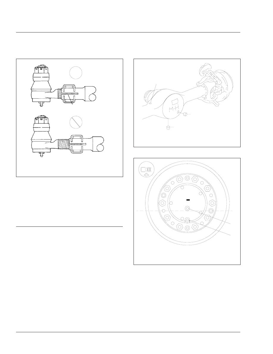
2.
The threaded portion of the tie-rod end assembly
must be inserted all the way into the cross-tube
split, for adequate clamping. See
. Replace
the parts if this cannot be done. For instructions,
see the axle manufacturer’s service manual.
3.
Check the tie-rod end nut and clamp nut torques.
Tighten the tie-rod end nut 100 lbf·ft (136 N·m),
and tighten the clamp nut 40 to 55 lbf·ft (54 to 75
N·m).
33–03 Tie-Rod End Lubricating
Wipe the tie-rod end grease fittings clean, then pump
multipurpose chassis grease (NLGI grade 1 or 2) to
the tie-rod ends until all used grease is forced out
and new grease appears at the ball stud neck.
33–04 All-Axle Alignment
Checking
Drive Axle Alignment Checking
Check the axle alignment, parallelism, and thrust
angle measurements for the rear drive axles. Use the
applicable procedure and specifications in Group 35
of the
Business Class
®
Trucks Service Manual
.
f320032a
1
1
A
10/20/93
A. Pump lubricant into each grease fitting until fresh
grease comes out here.
1.
Grease Fitting
Fig. 1, Meritor Front Axle
Front Axle
33
Business Class Trucks Maintenance Manual, June 2001
33/1
Toe-In Checking, Front Axle
See Group 33 of the
Business Class
®
Trucks Ser-
vice Manual
for wheel alignment procedures.
33–05 All-Wheel-Drive Front
Axle Oil Level Checking
1.
On all front-wheel-drive vehicles, check the oil
level in the differential. See
1.1
Remove the oil level check-and-fill plug,
and make sure the oil level is even with
the bottom of the bore.
1.2
If needed, add oil until the differential is
filled to the bottom of the bore.
1.3
Install the oil level check-and-fill plug, and
tighten it firmly.
2.
On front-wheel-drive vehicles equipped with
MT-17 axles, check the oil level in the hubs.
2.1
The oil drain bore must be at the bottom
in order to check the oil level. See
2.2
Remove the plug from the oil level check-
ing bore, and make sure the oil is level
with the bottom edge of the bore.
2.3
If needed, add oil until each axle hub is
filled to the bottom of the bore.
2.4
Install the plug in each oil level checking
bore, and tighten it firmly.
f320033a
1
10/20/93
OK
OK
NOTE: Pinch bolt not shown to provide clarity.
1.
Cross-Tube Split
Fig. 2, Tie-Rod End Adjustment
04/15/96
f350149
1
2
3
1.
Vent Valve
2.
Oil Level Check-and-Fill Plug
3.
Oil Drain Plug
Fig. 3, All-Wheel-Drive Front Axle Differential
04/10/96
A
M H
f350148
1
2
A. Correct Oil Level
1.
Oil Level Checking
Bore
2.
Oil Drain Bore
Fig. 4, All-Wheel-Drive Front Axle Hub, MT-17 Axles
Front Axle
33
Business Class Trucks Maintenance Manual, June 2001
33/2
Нет комментариевНе стесняйтесь поделиться с нами вашим ценным мнением.
Текст