Freightliner Business Class. Manual — part 23
Hendrickson Leaf Spring Assembly
Inspecting
1.
Inspect the spring hangers for wear of the spring
pin holes, cams, and the spring hanger legs.
2.
If equipped with the "RTE" or "UE" series, the
gap between the rear (No. 2) spring hanger and
the top spring leaf should measure at least 3/8
inch (9.5 mm) in an unloaded condition.
If the measurement is less than 3/8 inch (9.5
mm), install new rear (No. 3) extension hangers.
Lubricate the bolt threads with SAE 20 oil.
Tighten the 1/2–13 locknuts with hardened wash-
ers 85 lbf·ft (115 N·m).
3.
Inspect the spring leaves for cracks, gouges,
wear, or abnormal bends. The no. 1 main and
no. 2 wrapper spring leaves (the top two spring
leaves) may be individually replaced. If equipped
with the "RTE" or "UE" series suspension, the
nos. 1, 2, and 3 spring leaves (the top three
spring leaves) may be individually replaced. If a
spring leaf is damaged below these numbers in a
pack, replace the spring assembly. In addition,
replace both spring assemblies to ensure even
spring deflection.
Hendrickson Radius Rod Bushing
Checking
1.
Without detaching the torque arms, attempt to
move (by hand) each of the radius-rod ends up,
down, in, and out. If there is any movement, re-
place the torque arm.
2.
Inspect the rubber bushing ends. Replace the
torque arm if there are gaps between the rubber
bushing and the pin or the outer steel sleeve, if
either bushing end contacts a torque arm pin
mounting bolt, if there are cracks in the bushing,
or if part of the rubber bushing extends beyond
the outside diameter of the outer bushing sleeve.
Chalmers Suspension Inspecting
Chock the front wheels to prevent the vehicle from
moving. Place the transmission in neutral, and re-
lease the spring or driveline brakes before inspecting
the rear suspension.
Power wash the Chalmers rear suspension, or clean
it with a hard-bristle brush before performing a visual
inspection.
1.
Visually inspect the rubber bushings for cracks or
other damage.
Try to move the torque rod ends using your
hands only, and check for any free-play. If free-
play is felt, replace the torque rod end bushing.
Do not use a pry bar to check for free-play. Use
of a pry bar may lead to premature bushing re-
placement. See Group 32 of the
Business
Class
®
Trucks Service Manual
for replacement
instructions.
2.
If equipped with optional shock absorbers, check
for worn, broken, or damaged shock bushings,
heavy corrosion on the shock absorber body, or
fluid leaking from the shock absorber. Replace
the shock absorbers if any of these conditions
are found; see Group 32 of the
Business Class
®
Trucks Service Manual
.
3.
Lift the rear of the vehicle and support the frame
on jack stands to unload the suspension compo-
nents. The vehicle is lifted high enough when the
beam ends are off of the saddles. All jack stands
must be of sufficient strength and rigidity to
safely support the vehicle. Do not perform any
work on or around a vehicle that is supported
solely by a lifting device.
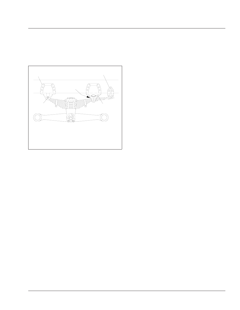
f320112a
05/27/93
1
2
3
4
A
A. Minimum gap of 3/8 inch (9.5 mm).
1.
Forward (no. 1) Spring Hanger
2.
Spring Eye Pin
3.
Rear (no. 2) Spring Hanger
4.
Rear (no. 3) Extension
Fig. 7, Unloaded RTE or UE Spring Suspension
Suspension
32
Business Class Trucks Maintenance Manual, July 1999
32/5
Visually inspect the walking beam for cracks, or
other damage. If damage is found, see Group
32 of the
Business Class
®
Trucks Service
Manual
for replacement instructions.
Keep the vehicle supported by the jack stands
for the next operation.
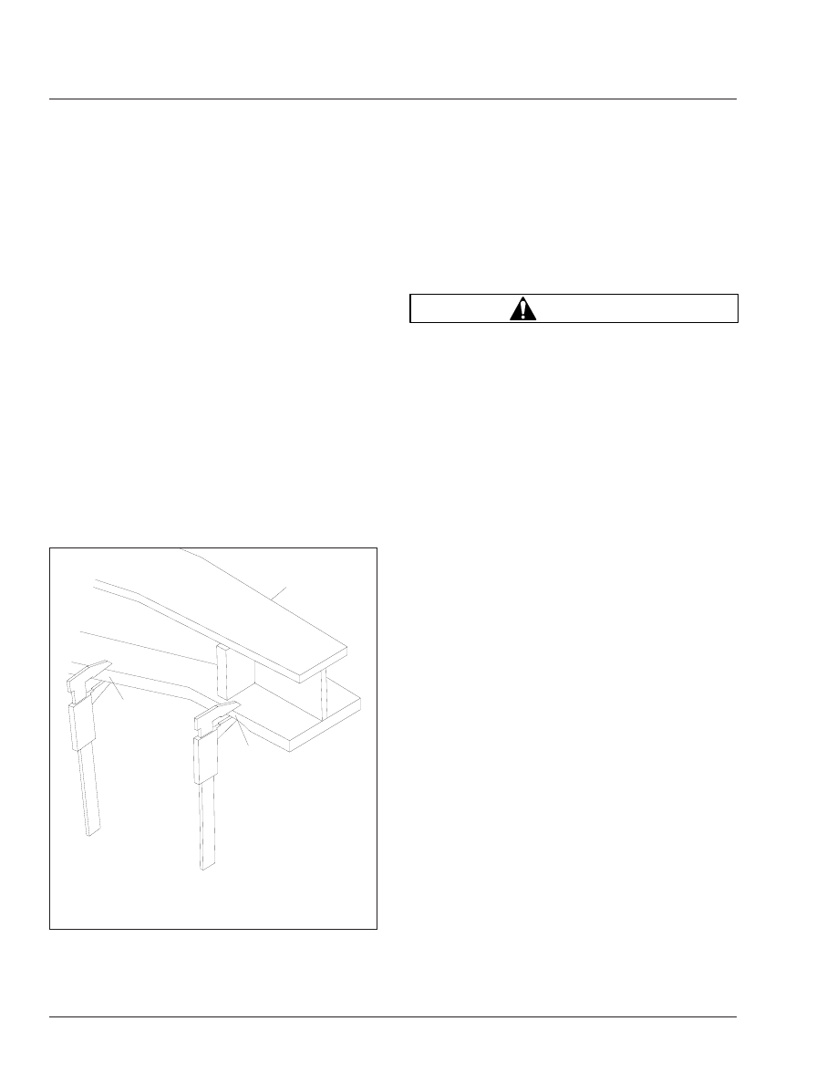
4.
Manipulate the walking beam so that a microme-
ter, vernier, or dial caliper can be used to deter-
mine the wear area thickness on the bottom
face. See
. Measurements should be taken
a minimum of 1/2 inch (13 mm) from the beam
flange edges to eliminate any edge wear that
may have occurred. Subtract the wear area
thickness (
, Ref. B), from the non-wear
area (
, Ref. A), to determine the amount of
wear.
If the beams show any wear greater than the
allowable 0.062-inch (1.5-mm) wear, a Chalmers
wear plate must be installed, or the walking
beam must be replaced. See Group 32 of the
Business Class
®
Trucks Service Manual
for re-
pair and replacement instructions.
5.
Rotate the restrictor cans 360 degrees and visu-
ally inspect the cans for cracks, severe corro-
sion, and distortion. If any of these conditions are
present, or the restrictor can is missing, replace
the restrictor can. See Group 32 of the
Business
Class
®
Trucks Service Manual
for replacement
instructions.
WARNING
Replace all cracked or missing restrictor cans.
Failure to do so could lead to loss of vehicle con-
trol, which could result in property damage, seri-
ous personal injury or death. Vehicles with
cracked or missing restrictor cans may be driven
slowly to the nearest workshop for restrictor can
replacement.
6.
Remove the jack stands, then lower the vehicle.
Check that the spring, or driveline brake is ap-
plied, then remove the wheel chocks.
Reyco 79KB Suspension Visual
Inspection
The Reyco 79KB suspension requires minimal main-
tenance. To provide trouble-free operation in over-
the-road applications, do the following visual inspec-
tion.
1.
Park the vehicle on level ground. Apply the park-
ing brakes, and chock the tires.
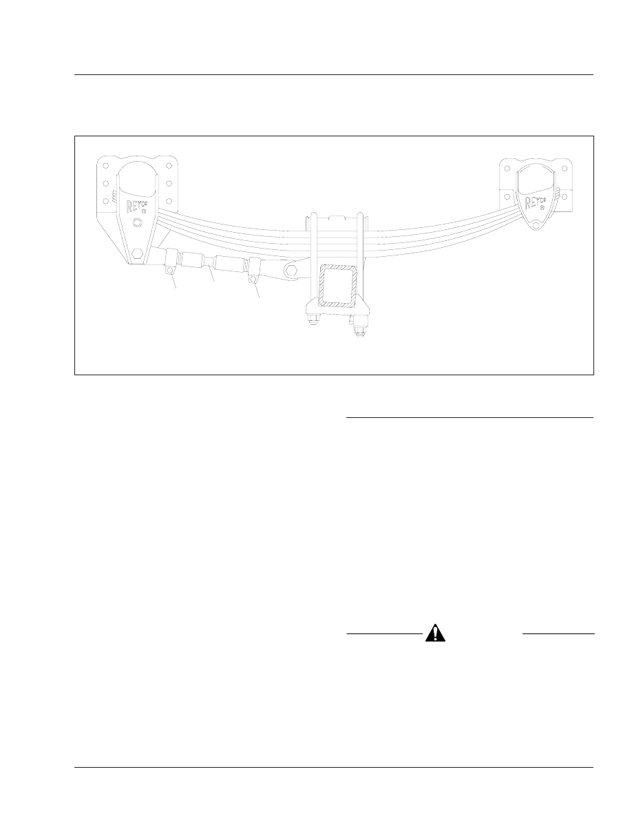
2.
Check that the torque rod clamps are directed
away from the spring to prevent possible interfer-
ence during operation. See
3.
Check the fit of springs to hangers to ensure
good ride characteristics.
4.
Check for elongated holes in the suspension
components. See Group 32 of the
Business
Class
®
Trucks Service Manual
for proper repair
procedures.
5.
Check bushing condition. Replace any bushing
that is worn, cracked, dry-rotted, or otherwise
damaged. See Group 32 of the
Business Class
®
Trucks Service Manual
for removal and installa-
tion instructions.
6.
Check tire condition. If abnormal tire wear is
found, check and replace all worn or damaged
components, and check suspension alignment.
See Group 32 of the
Business Class
®
Trucks
Service Manual
for component removal and in-
09/27/95
f320432
1
A
B
1.
Walking Beam
A. Non-Wear Area
B. Wear Area
Fig. 8, Walking Beam End Wear Thickness
Suspension
32
Business Class Trucks Maintenance Manual, July 1999
32/6
stallation procedures, and for suspension align-
ment instructions.
Reyco 79KB Fastener Torque Check
Check the U-bolt nuts, hanger mounting bolts, torque
rod clamp nuts, and the spring retainer bolts for
proper fastener torque.
1.
Park the vehicle on level ground. Apply the park-
ing brakes, and chock the tires.
2.
Use a click-type torque wrench to check that
U-bolt nuts are tightened 400 to 450 lbf·ft (540 to
610 N·m).
3.
Use a click-type torque wrench to check that
spring hanger bolts are tightened 190 lbf·ft (258
N·m).
4.
Use a click-type torque wrench to check that the
5/8-inch torque rod clamp nuts are tightened 125
to 150 lbf·ft (170 to 203 N·m).
5.
Use a click-type torque wrench to check that the
two end-nuts for each torque rod are tightened
400 to 450 lbf·ft (540 to 610 N·m).
6.
Use a click-type torque wrench to check that
spring retainer bolts are tightened 60 to 80 lbf·ft
(81 to 109 N·m).
32–02 Suspension Lubricating
Freightliner Spring Front Suspension
Wipe all dirt from the grease fittings at the forward
spring pin and the spring shackle pins; then apply
multipurpose chassis grease with a pressure gun un-
til the old grease is forced out.
Freightliner Spring Rear Suspension
Single Axle
Lubricate the spring pin by applying multipurpose
chassis grease at the grease fitting. See
. Lu-
bricate with a grease gun until grease appears at the
base of the fitting.
Tandem Axle
CAUTION
If the equalizer cap and tube assembly is
equipped with a nonrelief grease fitting, excessive
lubrication can damage the bushings.
Lubricate the equalizer cap-and-tube assembly bush-
ings by applying multipurpose chassis grease at the
pressure-relief grease fitting. See
. Lubricate
01/04/96
f320488
1
2
1
1.
Torque Rod Clamp
2.
Torque Rod
Fig. 9, Reyco 79KB Torque Rod Clamp Position
Suspension
32
Business Class Trucks Maintenance Manual, July 1999
32/7
with a hand gun or pressure gun until grease is
forced out from the base of the pressure-relief fitting.
Hendrickson Equalizer Beam End
Bushings and Rubber Center
Bushings
No lubrication is required for the equalizer beam end
bushings or equalizer beam rubber center bushings.
Hendrickson Spring Eye Pins, "RT,"
"RTE," "U," AND "UE" Series
Apply multipurpose chassis grease at the spring eye
pin grease fitting (located on the inboard side of the
spring eye pin) until clean grease appears at both
ends of the spring eye pin.
32–03 U-Bolt Torque Checking
Check the U-bolt torque of both the front and rear
axles (where applicable).
CAUTION
Failure to retorque the U-bolt nuts could result in
spring breakage and abnormal tire wear.
1.
Park the vehicle on a flat surface and apply the
parking brakes. Chock the tires to prevent the
vehicle from moving.
2.
Check the U-bolt torque in a diagonal pattern.
Set a click-type torque wrench to the highest
torque value for the fastener being checked. See
for U-bolt torque specifications. Turn the
wrench in a clockwise motion (looking up) until
the torque wrench clicks.
3.
Remove the chocks.
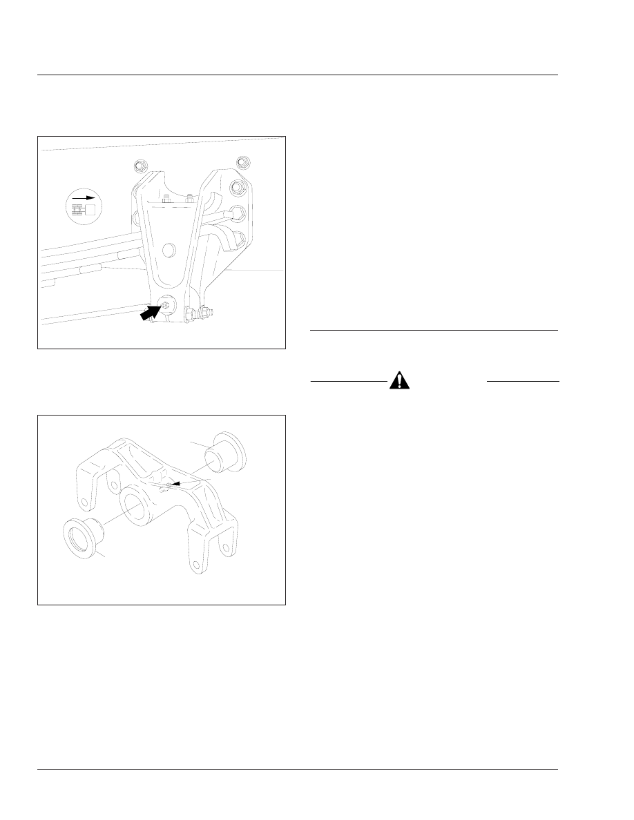
f320268a
10/05/94
Fig. 10, Forward Spring Bracket Spring Pin Grease
Fitting
320020a
05/27/93
1
1
A
A. Lubricate here.
1.
Cap-and-Tube Assembly Bushing
Fig. 11, Equalizer Assembly Lubrication
Suspension
32
Business Class Trucks Maintenance Manual, July 1999
32/8
Нет комментариевНе стесняйтесь поделиться с нами вашим ценным мнением.
Текст