Suzuki Grand Vitara JB627. Manual — part 117
1J-9 Charging System:
Generator Disassembly and Assembly
S6JB0B1A06005
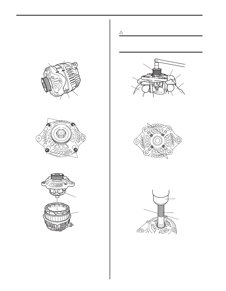
Disassembly
1) Put match marks at 2 locations (A (front housing (1)
and stator (2)) and B (rear housing (3) and stator
(2))) as shown in figure so that any possible mistake
can be avoided.
2) Loosen frame bolt (1).
3) Remove front housing with rotor (1) from stator (2).
4) Hold rotor by using vise (2) and loosen pulley nut
and then remove pulley (1).
CAUTION
!
When using vise, put clean cloth (3) and
aluminium plate (5) between rotor (4) and
vise (2) so as not to cause damage to rotor.
5) If required, remove drive end bearing.
a) Loosen retainer screw (1) and then remove
retainer.
b) Push out drive end bearing by using hydraulic
press (1) and special tool.
Special tool
(A): 09943–88211
1
2
3
(A)
(B)
I6JB011A0006-01
1
1
I6JB011A0007-01
1
2
I6JB011A0008-01
4
1
5
2
5
3
2
I6JB011A0009-01
1
1
I6JB011A0010-01
1
(A)
I6JB011A0011-01
Charging System: 1J-10
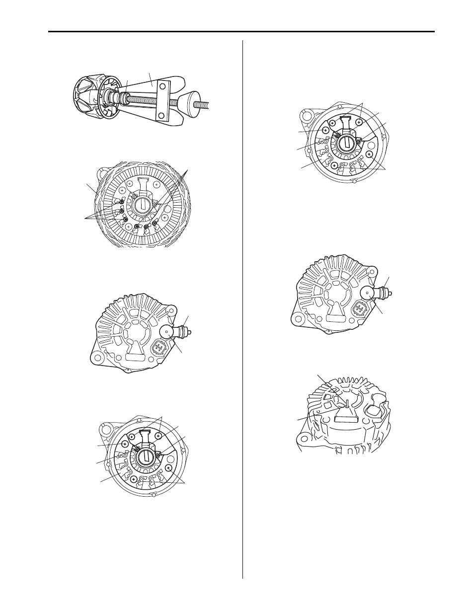
6) If required, use bearing puller (2) to remove rear end
bearing (1).
7) Loosen screw (1) and then remove stator (2) from
rear housing.
8) Remove cap (1).
9) Loosen “B” terminal nut and then remove insulator
(2).
10) Loosen screw (1) and then regulator assembly (2).
11) Loosen screw (3) and then remove rectifier (4).
Assembly
1) Install rectifier (4) to rear housing and then tighten
screw (3).
2) Install regulator assembly (2) to rear housing and
then tighten screw (1).
3) Install insulator (2) and then tighten “B” terminal nut
to specified torque.
Tightening torque
“B” terminal nut : 9 N·m (0.9 kgf-m, 7.0 lb-ft)
4) Install cap (1) to insulator (2).
5) Depress brush and then while holding it depressed,
and insert pin (1) to hole of rear housing (2).
1
2
I6JB011A0012-01
1
1
2
I6JB011A0013-01
1
2
I6JB011A0014-01
3
1
4
3
1
2
1
I6JB011A0015-01
3
1
4
3
1
2
1
I6JB011A0015-01
1
2
I6JB011A0014-01
1
2
I6JB011A0016-01

1J-11 Charging System:
6) Install stator (2) to rear housing by aligning match
marks provided before removal and then tighten
screw (1).
7) If rear end bearing (2) is removed, install it by using
hydraulic press (1).
8) If drive end bearing is removed, install it.
a) Press-fit drive end bearing by using hydraulic
press (1) and special tool.
Special tool
(A): 09913–76010
b) Install retainer and then tighten retainer screw
(1).
9) Insert stator to front housing and install pulley and
pulley nut.
10) Hold rotor by using vise (1) and tighten pulley nut to
specified torque.
CAUTION
!
When using vise, put clean cloth (2) and
aluminium plate (3) between rotor (4) and
vise (1) so as not to cause damage to rotor.
Tightening torque
Pulley nut: 118 N·m (11.8 kgf-m, 85.5 lb-ft)
11) Install front housing with rotor (1) to stator (2) by
aligning match marks provided before removal and
then tighten frame bolt (3) to specified torque.
Tightening torque
Frame bolt (a): 4 N·m (0.4 kgf-m, 3.0 lb-ft)
1
1
2
I6JB011A0013-01
2
1
I6JB011A0017-01
1
A
I6JB011A0018-02
1
1
I6JB011A0010-01
4
3
1
2
1
I6JB011A0019-01
1
2
3,(a)
3,(a)
I6JB011A0020-01

Charging System: 1J-12
12) Remove pin (1) from rear housing (2).
13) Make sure that rotor turns smoothly.
Generator Inspection
S6JB0B1A06006
Rotor
• Using ohmmeter, check for continuity between slip
rings of rotor. If there is no continuity, replace rotor.
Standard resistance between clip rings of rotor
2.0 – 2.3
Ω at 20 °C (68 °F)
• Using ohmmeter, check that there is no continuity
between slip ring and rotor. If there is continuity,
replace rotor.
Stator
• Check resistance between the following leads of
stator. if there is no continuity, replace stator.
• Using ohmmeter, check that there is no continuity
between coil leads (1) and stator core (2). If there is
continuity, replace stator.
Brush and Brush Holder
Check each brush for wear by measuring its length as
shown. Replace the brush if the brush is found worn
down to service limit line (1).
1
2
I6JB011A0016-01
IYSQ011A0042-01
IYSQ011A0043-01
stator lead
Resistance
1 – 2
continuity
1 – 3
4 – 5
4 – 6
1
2
3
4
5
6
I6JB011A0021-01
2
1
I6JB011A0022-01
I6JB011A0023-03
Нет комментариевНе стесняйтесь поделиться с нами вашим ценным мнением.
Текст