Suzuki Grand Vitara JB627. Manual — part 115

1J-1 Charging System:
Engine
Charging System
General Description
Battery Description
S6JB0B1A01001
The battery has three major functions in the electrical system.
• It is a source of electrical energy for cranking the engine.
• It acts as a voltage stabilizer for the electrical system.
• It can, for a limited time, provide energy when the electrical load exceeds the output of the generator.
Carrier and Hold-Down
The battery carrier should be in good condition so that it will support the battery securely and keep it level.
Before installing the battery, the battery carrier and hold-down clamp should be clean and free from corrosion and
make certain there are no parts in carrier.
To prevent the battery from shaking in its carrier, the hold-down bolts should be tight enough but not over-tightened.
Electrolyte Freezing
The freezing point of electrolyte depends on its specific gravity. Since freezing may ruin a battery, it should be
protected against freezing by keeping it in a fully charged condition. If a battery is frozen accidentally, it should not be
charged until it is warmed.
Sulfation
If the battery is allowed to stand for a long period in discharged condition, the lead sulfate becomes converted into a
hard, crystalline substance, which will not easily turn back to the active material again during the subsequent
recharging. “Sulfation” means the result as well as the process of that reaction.
Such a battery can be revived by very slow charging and may be restored to usable condition but its capacity is lower
than before.
Built-In Indicator (If Equipped)
The battery has a built-in temperature compensated indicator (1) in the top of the battery. This indicator is to be used
with the following diagnostic procedure.
When checking the indicator, make sure that the battery has a clean top. A light may be needed in some poorly-lit
areas.
Three types of indication available under normal operation are as follows.
IYSQ011A0001-01

Charging System: 1J-2
• Green dot:
Battery is sufficiently charged for testing.
• Dark:
Battery must be charged before testing.
If there is a cranking complaint, battery should be tested as described in “Battery Inspection”.
Charging and electrical systems should also be checked at this time.
• Clear or light yellow:
This means that fluid level is below the bottom of hydrometer. Its possible cause is excessive or prolonged
charging, a broken case, excessive tipping or normal battery deterioration.
When the battery is found in such condition, it is possible that high charging voltage is caused by the faulty charging
system and therefore, charging and electrical systems need to be checked. If there is a trouble in cranking and its
cause lies in the battery, it should be replaced.
Generator Description
S6JB0B1A01002
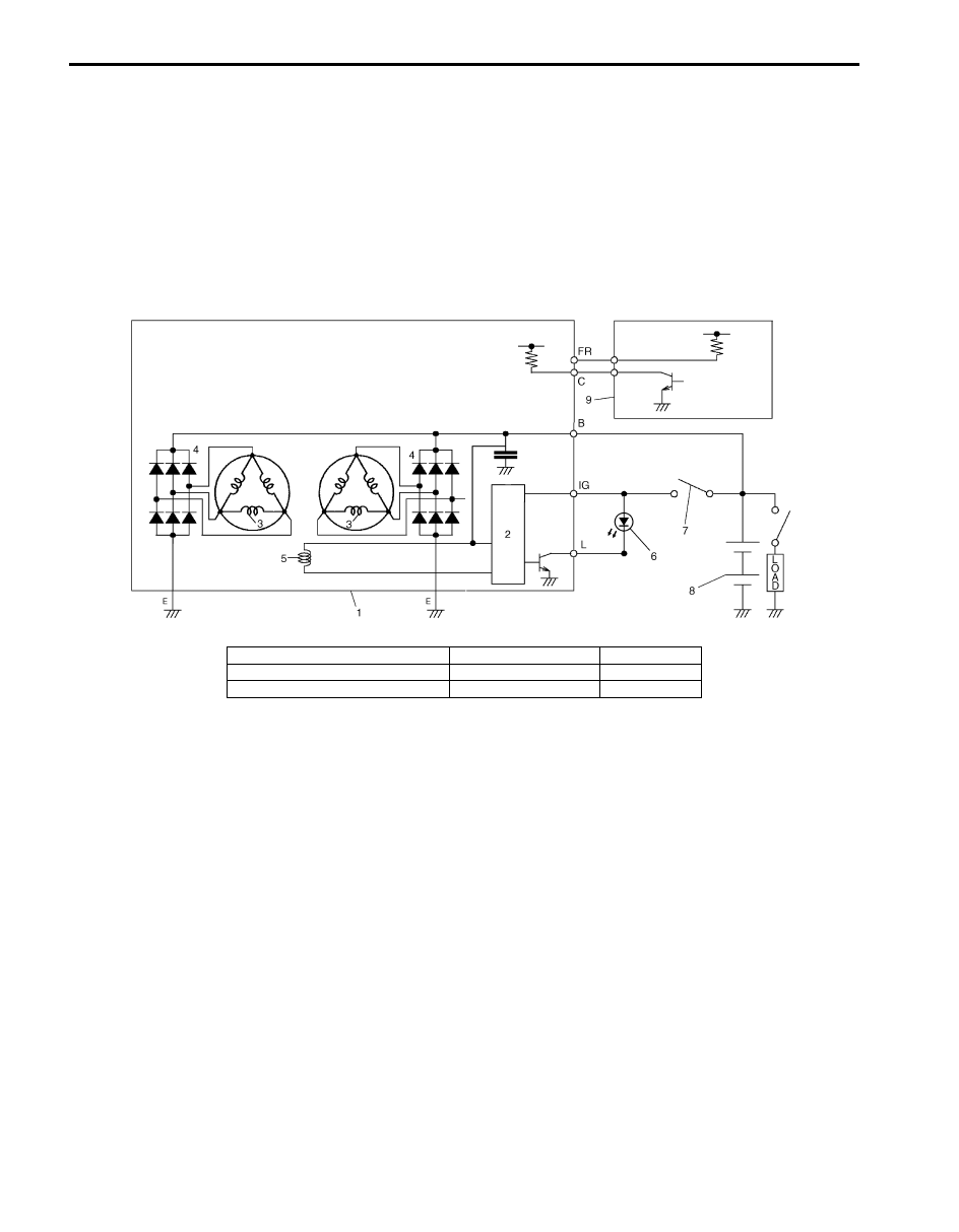
The basic charging system is the IC integral regulator charging system. The internal components are connected
electrically as shown below.
Diagnosis
OK
Charging Necessary
Low Level Electrolyte
Replace Battery
Indicator
Green dot
Dark
Clear
Gravity Ball
IYSQ011A0002-01
IYSQ011A0065-01
IYSQ011A0066-01
IYSQ011A0067-01
IYSQ011A0068-01
IYSQ011A0069-01
I6JB011A0001-01
1. Pulley
6. Field coil
11. Rear housing
IG: Ignition terminal
2. Pulley nut
7. Rectifier
B: Generator output (Battery terminal)
L: Lamp terminal
3. Rotor fan
8. Brush
C: Generator cut
4. Stator coil
9. Regulator
E: Ground
5. Stator core
10. Front housing
FR: Field duty monitor
1J-3 Charging System:
Wiring Circuit
The generator features a solid state regulator that is mounted inside the generator. All regulator components are
enclosed into a solid mold, and this unit along with the brush holder assembly is attached to the rear housing.
The generator rotor bearings contain enough grease to eliminate the need for periodic lubrication.
Two brushes carry current through the two slip rings to the field coil mounted on the rotor, and under normal conditions
will provide long period of attention-free service.
The stator windings are assembled inside a laminated core that forms part of the generator frame.
A rectifier bridge connected to the stator windings contains diodes, and electrically changes the stator A.C. voltages to
a D.C. voltage which appears at the generator output terminal.
The neutral diodes serve to convert the voltage fluctuation at the neutral point to direct current for increasing the
generator output.
Diagnostic Information and Procedures
Battery Inspection
S6JB0B1A04001
Common Causes of Failure
A battery is not designed to last indefinitely; however, with proper care, it will provide many years of service. If the
battery performs satisfactorily during test but fails to operate properly for no apparent reason, the following are some
factors that may point to the cause of trouble:
• Accessories left on overnight or for an extended period without the generator operating.
• Slow average driving speeds for short periods.
• Electrical load exceeding generator output particularly with addition of aftermarket equipment.
• Defects in charging system such as high resistance, slipping drive belt, loose generator output terminal, faulty
generator or voltage regulator. Refer to “Generator Symptom Diagnosis”.
• Battery abuse, including failure to keep battery cable terminals clean and tight or loose battery hold down.
• Mechanical problems in electrical system such as shorted or pinched wires.
Visual inspection
Check for obvious damage, such as cracked or broken case or cover, that could permit loss of electrolyte.
If obvious damage is noted, replace battery. Determine cause of damage and correct as needed.
I6JB011A0002-01
1. Generator with regulator assembly
4. Diode
7. Main switch
2. I.C. regulator
5. Field coil (rotor coil)
8. Battery
3. Stator coil
6. Charge indicator light
9. ECM
Charging System: 1J-4
Generator Symptom Diagnosis
S6JB0B1A04002
A charging circuit wiring diagram for generator connection is shown in “Generator Description”. To avoid damage,
always follow these precautions:
CAUTION
!
• Do not mistake polarities of “IG” terminal and “L” terminal.
• Do not create a short circuit between “IG” and “L” terminals. Always connect these terminals
through a lamp.
• Do not connect any load between “L” and “E”.
• When connecting charger or booster battery to vehicle battery, see “Jump Starting in Case of
Trouble in charging system will show up as one or more of the following conditions:
1) Faulty charge indicator light operation.
2) Undercharged battery as evidenced by slow cranking or indicator clear with red dot.
3) Overcharged battery as evidenced by excessive spewing of electrolyte from vents.
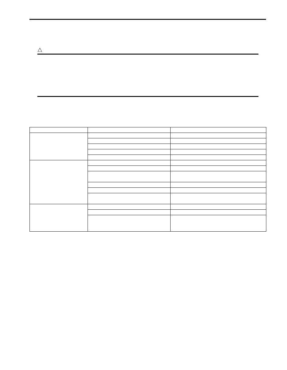
Condition
Possible cause
Correction / Reference Item
Noisy generator
Loose drive belt
Adjust or replace drive belt.
Loose drive belt pulley
Check generator.
Loose mounting bolts
Check mounting condition.
Worn or dirty bearings
Check generator.
Defective diode or stator
Check generator.
Charge indicator light
does not light with
ignition ON and engine
OFF
Fuse blown
Check fuse.
Light burned out
Replace light.
indicator lamp (LED) faulty
Check BCM, combination meter and/or CAN
communication line.
Wiring connection loose
Tighten loose connection.
IC regulator or field coil faulty
Check generator.
Poor contact between brush and slip
ring
Repair or replace.
Charge indicator light
does not go out with
engine running
Battery requires frequent
recharging
Drive belt loose or worn
Adjust or replace drive belt.
IC regulator or generator faulty
Check charging system.
Wiring faulty
Repair wiring.
Нет комментариевНе стесняйтесь поделиться с нами вашим ценным мнением.
Текст