Suzuki Grand Vitara JB627. Manual — part 116
1J-5 Charging System:
Generator Test (Undercharged Battery Check)
S6JB0B1A04003
This condition, as evidenced by slow cranking or
indicator clear with red dot can be caused by one or
more of the following conditions even though indicator
lamp may be operating normal.
The following procedure also applies to cars with
voltmeter and ammeter.
1) Make sure that undercharged condition has not been
caused by accessories left on for extended period of
time.
2) Check drive belt for proper tension.
3) If battery defect is suspected, refer to “Battery
4) Inspect wiring for defects. Check all connections for
tightness and cleanliness, battery cable connections
at battery, starting motor and ignition ground cable.
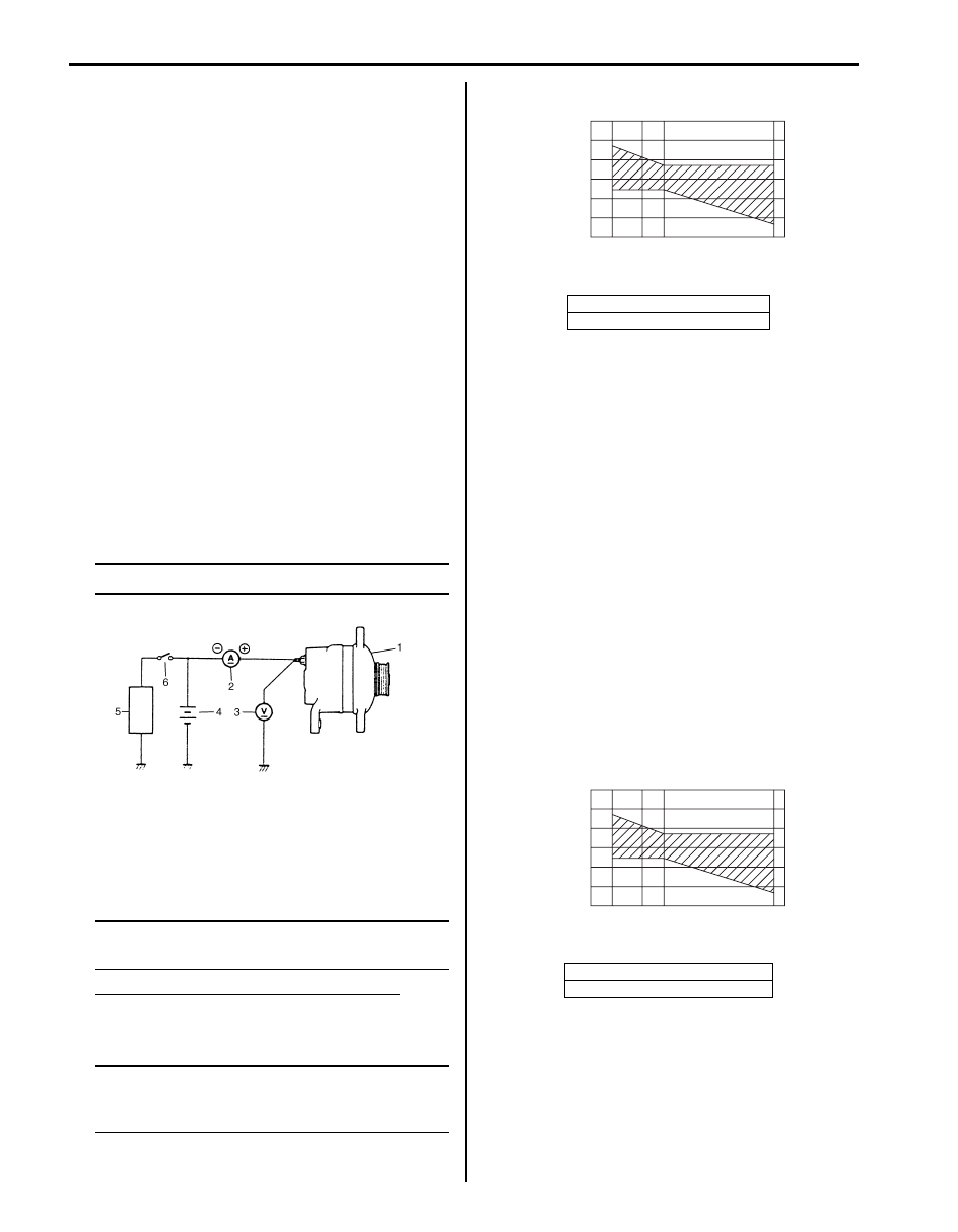
5) Connect switch (6), load (5), battery (4), voltmeter
(3) and ammeter (2) to generator (1) as shown in
figure.
Voltmeter: Set between generator “B” terminal
and ground.
Ammeter: Set between generator “B” terminal
and battery (+) terminal.
NOTE
Use fully charged battery.
6) Measure current and voltage.
No-Load Check
1) Run engine from idling up to 2000 rpm and read
meters.
NOTE
Turn off switches of all accessories (wiper,
heater etc.).
Specification for undercharged inspection
Current: 10 A
Voltage (at 20
°C (68 °F)): 14.2 – 14.8 V
NOTE
Consideration should be taken that voltage
will differ somewhat with regulator case
temperature as shown in the figure.
• If voltage is higher than standard value
If voltage is higher than standard value, check ground
of brushes.
If brushes are not grounded, replace IC regulator.
• If voltage is lower than standard value
If voltage is lower than standard value, check rotor
and stator, rectifier, brushes, regulator.
Load Check
1) Run engine at 2000 rpm and turn on head light and
heater motor.
2) Measure current and if it is less than 30 A repair or
replace generator.
Generator Test (Overcharged Battery Check)
S6JB0B1A04004
1) To determine battery condition, refer to “Battery
2) If obvious overcharge condition exists as evidenced
by excessive spewing of electrolyte, measure
generator “B” terminal voltage at engine 2000 rpm.
3) If measured voltage is higher than upper limit value,
proceed to “Generator Disassembly and Assembly”.
4) Check ground of brushes. If brushes are not
grounded, replace IC regulator. Then check field coil
for grounds and shorts, referring to “Generator
Inspection”.
IYSQ011A0007-01
[A]: Regulated voltage (V)
[B]: Heat sink temperature (
°C)
[A]: Regulated voltage (V)
[B]: Heat sink temperature (
°C)
16.0
15.5
14.3
15.2
14.8
14.2
13.3
14.6
15.0
14.5
14.0
13.5
13.0
-30
0
20
[A]
[B]
68
22
120 (˚C)
248 (˚F)
(V)
I5JB0A1A0006-02
16.0
15.5
14.3
15.2
14.8
14.2
13.3
14.6
15.0
14.5
14.0
13.5
13.0
-30
0
20
[A]
[B]
68
22
120 (˚C)
248 (˚F)
(V)
I5JB0A1A0006-02

Charging System: 1J-6
Repair Instructions
Jump Starting in Case of Emergency
S6JB0B1A06001
With Auxiliary (Booster) Battery
CAUTION
!
Do not push or tow vehicle to start. Damage
to emission system and/or to other parts of
vehicle may result.
Both booster and discharged battery should be treated
carefully when using jumper cables. Follow procedure
outlined below, being careful not to cause sparks.
WARNING
!
• Departure from these conditions or
procedure described below could result in:
a. Serious personal injury (particularly to
eyes) or property damage from such
causes as battery explosion, battery
acid, or electrical burns.
b. Damage to electronic components of
either vehicle.
• Never expose battery to open flame or
electric spark. Batteries generate gas
which is flammable and explosive.
• Remove rings, watches, and other jewelry.
Wear approved eye protection.
• Do not allow battery fluid to contact eyes,
skin, fabrics, or painted surface as fluid is
a corrosive acid. Flush any contacted area
with water immediately and thoroughly.
• Be careful so that metal tools or jumper
cables do not contact positive battery
terminal (or metal in contact with it) and
any other metal on vehicle, because a
short circuit could occur.
• Batteries should always be kept out of
reach of children.
1) Set parking brake and place automatic transmission
in PARK (NEUTRAL on manual transmission).
2) Turn OFF ignition switch, turn OFF lights and all
other electrical loads.
3) Check built-in indicator (if equipped). If it is clear or
light yellow, replace the battery.
4) Attach end of one jumper cable to positive terminal
of booster battery and the other end of the same
cable to positive terminal of discharged battery. (Use
12-volt battery only to jump start engine).
5) Attach one end of the remaining negative cable to
negative terminal of booster battery, and the other
end to a solid engine ground (such as exhaust
manifold) at least 45 cm (18 in.) away from battery of
vehicle being started.
WARNING
!
Do not connect negative cable directly to
negative terminal of dead battery.
6) Start engine of vehicle that is providing jump start
and turn off electrical accessories. Then Start engine
of the vehicle with discharged battery.
7) Reverse connecting procedure exactly when
disconnecting jumper cable. Negative cable must be
disconnected from engine that was jump started first.
With Charging Equipment
CAUTION
!
When jump starting engine with charging
equipment, be sure equipment used is 12-
volt and negative ground. Do not use 24-volt
charging equipment. Using such equipment
can cause serious damage to electrical
system or electronic parts.
1J-7 Charging System:
Battery Dismounting and Remounting
S6JB0B1A06002
WARNING
!
When handling battery, following safety
precautions should be followed:
• Hydrogen gas is produced by battery. A
flame or spark near battery may cause the
gas to ignite.
• Battery fluid is highly acidic. Avoid spilling
on clothing or other fabric. Any spilled
electrolyte should be flushed with large
quantity of water and cleaned immediately.
Dismounting
1) Disconnect negative cable.
2) Disconnect positive cable.
3) Remove retainer.
4) Remove battery.
Handling
When handling battery, the following safety precautions
should be followed:
• Hydrogen gas is produced by battery. A flame or
spark near battery may cause the gas to ignite.
• Battery fluid is highly acidic. Avoid spilling on clothing
or other fabric. Any spilled electrolyte should be
flushed with large quantity of water and cleaned
immediately.
Remounting
1) Reverse removal procedure.
2) Torque battery cables securely.
NOTE
Check to be sure that ground cable has
enough clearance to hood panel by terminal.
Generator Dismounting and Remounting
S6JB0B1A06003
Dismounting
1) Disconnect negative (–) cable at battery.
2) Remove air cleaner case and hose.
3) Disconnect generator lead wire (“B” terminal wire)
and coupler from generator.
4) Remove water pump and generator drive belt. Refer
to “Water Pump and Generator Drive Belt Removal
and Installation”.
5) Remove generator bracket bolt and then remove
bracket.
6) Remove generator mounting bolt.
7) Remove generator.
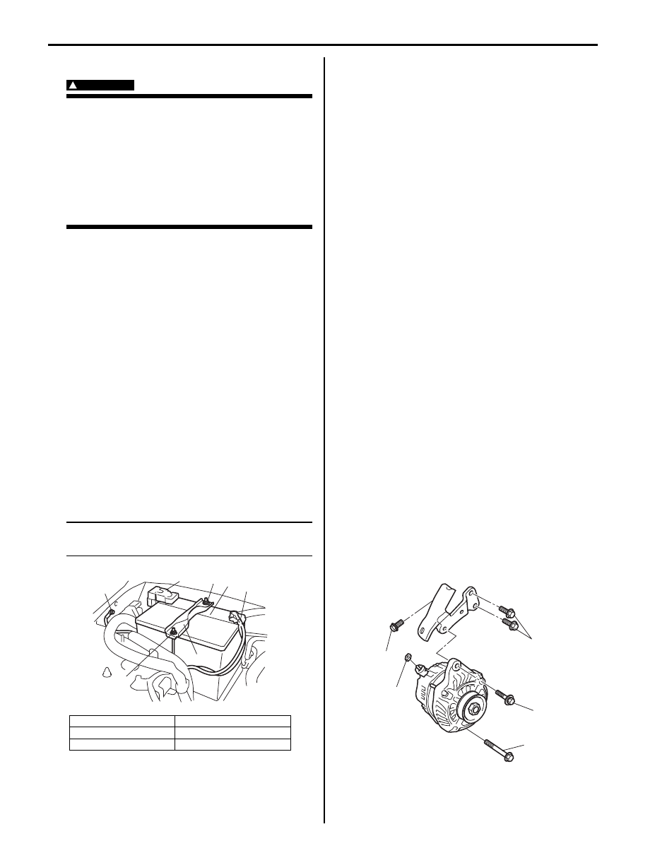
Remounting
1) Install bracket and then tighten generator bracket
bolt (3) to specified torque.
Tightening torque
Generator bracket bolt (c): 45 N·m (4.5 kgf-m,
32.5 lb-ft)
2) Mount generator on the generator bracket.
3) Tighten generator mounting bolt (upper bolt (short)
(1), lower bolt (long) (2)).
Tightening torque
Generator mounting upper bolt (a): 25 N·m (2.5
kgf-m, 18.0 lb-ft)
Generator mounting lower bolt (b): 45 N·m (4.5
kgf-m, 32.5 lb-ft)
4) Install water pump and generator drive belt. Refer to
“Water Pump and Generator Drive Belt Removal and
Installation”.
5) Connect “B” terminal wire and coupler to generator.
Tightening torque
“B” terminal outer nut (d): 7 N·m (0.7 kgf-m, 5.0
lb-ft)
6) Install air cleaner case and hose.
7) Connect negative (–) cable at battery.
1. Battery
4. Body ground bolt
2. Positive cable
5. Retainer
3. Negative cable
6. Nut
4
2
6
5
3
1
6
I6JB011A0003-01
1,(a)
2,(b)
3,(c)
3,(c)
(d)
I6JB011A0004-01

Charging System: 1J-8
Generator Components
S6JB0B1A06004
7
8
2
1
3
4
5
6
9
10
11
12
13
15
16
14
(a)
(c)
(b)
(b)
(b)
I6JB011A0005-02
1. Pulley nut
6. Driver end bearing
11. Rear housing
16. “B” terminal nut
2. Pulley
7. Bearing retainer
12. Rectifier
: 118 N
⋅m (11.8 kgf-m, 85.5 lb-ft)
3. Front housing
8. Rotor
13. Regulator assembly
: 4 N
⋅m (0.4 kgf-m, 3.0 lb-ft)
4. Stator
9. Rear end bearing
14. Generator stay bushing
: 9 N
⋅m (0.9 kgf-m, 7.0 lb-ft)
5. Frame bolt
10. Retainer screw
15. “B” terminal
Нет комментариевНе стесняйтесь поделиться с нами вашим ценным мнением.
Текст