Suzuki Grand Vitara JB627. Manual — part 420

10B-29 Body Electrical Control System:
7
DTC check of BCM
1) Disconnect connector of any one of control module other
than BCM.
2) Recheck DTC for BCM.
Is DTC U1144 (No.1144) detected?
Disconnect connectors
of control modules other
than the one whose
connector is
disconnected in Step 1)
one by one and check
that DTC U1144 is
detected by BCM each
time connector is
disconnected. When
DTC U1144 is not
detected by BCM while
checking in this way, go
to description under
“NO” below. If DTC
U1144 is detected by
BCM even when
connectors of all control
modules that use CAN
communication with
BCM are disconnected,
substitute a known-
good BCM and recheck.
Check power and
ground circuit of control
module disconnected in
Step 1). If circuit is OK,
substitute a known-
good control module
disconnected in Step 1)
and recheck.
Step
Action
Yes
No
Body Electrical Control System: 10B-30
Inspection of BCM and Its Circuits
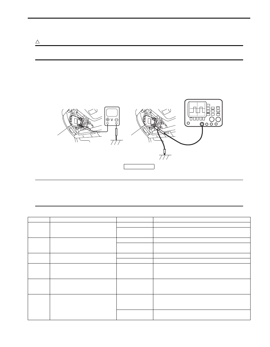
S6JB0BA204017
BCM and its circuits can be checked at BCM wiring couplers by measuring voltage and resistance.
CAUTION
!
BCM cannot be checked by itself. It is strictly prohibited to connect voltmeter or ohmmeter to BCM
with couplers disconnected from it.
Voltage Check
1) Disconnect negative cable (–) at battery.
2) Remove steering column hole cover from instrument panel.
3) Check voltage at each terminal number of couplers connected.
For connector and terminal number, refer to “Connector Layout Diagram of BCM”.
NOTE
• As each terminal voltage is affected by the battery voltage, confirm that it is 11 V or more when
ignition switch is ON.
• Voltage with asterisk (*) can not be measured by voltmeter because it is pulse signal.
Check it with oscilloscope if necessary.
BCM connector “G30”
1
1
I5JB0AA20012-01
1. BCM
Terminal
Circuit
Normal voltage
Condition
G30-1
Ignition switch signal (IG ON)
10 – 14 V
Ignition switch is at ON position
0 V
Ignition switch is at any position other than ON
position
G30-2
Power source (ACC)
10 – 14 V
Ignition switch is at ACC or ON position
0 V
Ignition switch is at any position other than ACC or
ON position
G30-3
Key reminder switch
10 – 14 V
Ignition key is inserted to ignition key cylinder
0 V
Ignition key is pulled out from ignition key cylinder
G30-4
Serial communication line for
HVAC control module
*0 – 1 V
↑↓
10 – 14 V
Refer to “Reference waveform No. 1: ”
G30-5
Serial communication line for
information display and HVAC
control module
*0 – 1V
↑↓
10 – 14 V
Refer to “Reference waveform No. 2: ”
G30-6
Rear wiper switch
*0 – 1 V
↑↓
10 – 14 V
Refer to “Reference waveform No. 3: ”
0 V
Ignition switch is at ON position and rear wiper
switch is at ON position

10B-31 Body Electrical Control System:
BCM connector “G31”
G30-7
Rear wiper INT switch
*0 – 1 V
↑↓
10 – 14 V
Refer to “Reference waveform No. 3: ”
0 V
Ignition switch is at ON position and rear wiper
switch is at INT position
G30-8
—
—
—
G30-9
Front fog light switch (if equipped)
10 – 14 V
Lighting switch is at CLEARANCE position and
front fog light switch is at ON position
0 V
Lighting switch is at CLEARANCE position and
front fog light switch is at OFF position
G30-10 Lighting switch (HEAD)
10 – 14 V
Lighting switch is at any position other than HEAD
position
0 V
Lighting switch is at HEAD position
G30-11 Lighting switch (CLEARANCE)
10 – 14 V
Lighting switch is at OFF position
0 V
Lighting switch is at any position other than OFF
position
G30-12 Ground for BCM
0 V
Ignition switch is at each position
G30-13
—
—
—
G30-14
—
—
—
G30-15
—
—
—
G30-16 Theft deterrent light
10 – 14 V
Theft deterrent light is not lit up
0 V
Theft deterrent light is lit up
G30-17
—
—
—
G30-18
—
—
—
G30-19 Serial communication line of SDM
*0 – 1 V
↑↓
4 – 6 V
Refer to “Reference waveform No. 4: ”
G30-20
—
—
—
G30-21
Lighting switch (AUTO) (if
equipped)
10 – 14 V
Lighting switch is at other than AUTO position
0 V
Lighting switch is at AUTO position
G30-22
Vehicle speed signal output (if
equipped)
*0 – 1 V
↑↓
10 – 14 V
Refer to “Reference waveform No. 5: ”
G30-23
—
—
—
G30-24
—
—
—
Terminal
Circuit
Normal voltage
Condition
Terminal
Circuit
Normal voltage
Condition
G31-1
CAN communication line (high) for
each control module
*2.5 – 3.6 V
Refer to “Reference waveform No. 6: ”
G31-2
CAN communication line (high) for
DLC
*2.5 – 3.6 V
G31-3
CAN communication line (low) for
each control module
*1.6 – 2.5 V
G31-4
CAN communication line (low) for
DLC
*1.6 – 2.5 V
G31-5
—
—
—
G31-6
—
—
—
G31-7
Brake fluid level switch
*5 – 12 V
Refer to “Reference waveform No. 7: ”
0 V
Ignition switch is at ON position and brake fluid
level is lower than MIN level
G31-8
Parking brake switch
*5 – 12 V
Refer to “Reference waveform No. 7: ”
0 V
Ignition switch is at ON position and parking brake
lever is pulled up
G31-9
Oil pressure switch
*6 – 14 V
Refer to “Reference waveform No. 8: ”
0 V
Ignition switch is at ON position and engine is at
stop
G31-10 Generator “L” terminal
10 – 14 V
Engine is running
0 V
Ignition switch is at ON position

Body Electrical Control System: 10B-32
G31-11
—
—
—
G31-12 Tail light relay control
10 – 14 V
Lighting switch is at OFF position
0 V
Lighting switch is at any position other than OFF
position
G31-13 Rear wiper control
10 – 14 V
Ignition switch is at ON position and rear wiper is
not in operation
0 V
Ignition switch is at ON position and rear wiper is in
operation
G31-14
Rear end door window defogger
control
10 – 14 V
Engine is running and rear end door window
defogger is not in operation
0 V
Engine is running and rear end door window
defogger is in operation
G31-15 Horn control
10 – 14 V
Horn is not in operation
0 V
Horn is in operation
G31-16 DRL control (if equipped)
10 – 14 V
Engine is running and lighting switch is at
CLEARANCE or OFF position
0 V
Engine is running and lighting switch is at HEAD
position
G31-17 Front fog light control (if equipped)
10 – 14 V
Lighting switch is at CLEARANCE position and
front fog light switch is at OFF position
0 V
Lighting switch is at CLEARANCE position and
front fog light switch is at ON position
G31-18
Power supply for keyless entry
receiver (if equipped)
4 – 6 V
Ignition switch is at ON position
G31-19
Signal for keyless entry receiver (if
equipped)
*0 – 1 V
↑↓
4 – 6 V
Refer to “Reference waveform No. 9: ”
G31-20
Ground for keyless entry receiver
(if equipped)
0 V
Ignition switch is at each position
G31-21
Sensor ground for outside air
temperature sensor
0 V
Ignition switch is at each position
G31-22
Sensor ground for auto light
sensor (if equipped)
0 V
Ignition switch is at each position
G31-23
Auto-on headlight sensor (if
equipped)
0.2 V
Ignition switch is at ON position and cover auto-on
headlight sensor lens by hand
3 – 4 V
Ignition switch is at ON position and light auto-on
headlight sensor lens by 100 W lights
G31-24 Outside air temperature sensor
About 1.5 V
Ignition switch is at ON position and outside air
temperature approx. 20
°C (68 °F)
G31-25
Power supply for auto light sensor
(if equipped)
4 – 6 V
Ignition switch is at ON position
G31-26 Manual door lock switch (Unlock)
4 – 6 V
Manual door lock switch is at any position other
than unlock position
0 V
Manual door lock switch is at unlock position
G31-27 Manual door lock switch (Lock)
4 – 6 V
Manual door lock switch is at any position other
than lock position
0 V
Manual door lock switch is at lock position.
G31-28
Power/Normal mode switch (A/T
model)
4 – 6 V
Ignition switch is at ON position and Power/Normal
mode switch is at ON position
0 V
Ignition switch is at ON position and Power/Normal
mode switch is at OFF position
G31-29
—
—
—
G31-30
—
—
—
G31-31
—
—
—
G31-32
—
—
—
G31-33
—
—
—
G31-34
Turn signal / hazard warning relay
control
0 V
Hazard warning switch is at ON position
10 – 14 V
Hazard warning switch is at OFF position
G31-35 Serial communication line of DLC
7 – 12 V
Ignition switch is at ON position
Terminal
Circuit
Normal voltage
Condition
Нет комментариевНе стесняйтесь поделиться с нами вашим ценным мнением.
Текст