Suzuki Grand Vitara JB627. Manual — part 421

10B-33 Body Electrical Control System:
BCM connector “G32”
G31-36
Driver side door key cylinder
switch (Unlock)
10 – 14 V
Driver side key cylinder switch is at any position
other than unlock position
0 V
Driver side key cylinder switch is at unlock position
G31-37
Driver side door key cylinder
switch (lock)
10 – 14 V
Driver side key cylinder switch is at any position
other than lock position
0 V
Driver side key cylinder switch is at lock position
G31-38
Door switch (rear end door and
other than driver side door)
10 – 14 V
Rear right and left side door, passenger side door
and rear end door are closed
0 V
Any one of the door is opened (except driver side
door)
G31-39 Driver side door switch
10 – 14 V
Driver side door is closed
0 V
Driver side door is opened
G31-40 Driver seat belt switch
*5 – 12 V
Refer to “Reference waveform No. 7: ”
0 V
Ignition switch is at ON position and driver seat
belt is unfastened
Terminal
Circuit
Normal voltage
Condition
Terminal
Circuit
Normal voltage
Condition
G32-1
Ground for BCM
0 V
Ignition switch is at each position
G32-2
Rear door lock actuator control
(Unlock)
10 – 14 V
Unlock signal is output for rear door lock actuators
0 V
Unlock signal is not output for rear door lock
actuators
G32-3
Door lock actuator control (Lock)
10 – 14 V
Lock signal is output for all door lock actuators
0 V
Lock signal is not output for all door lock actuators
G32-4
—
—
—
G32-5
Power supply for door lock
actuator
10 – 14 V
Ignition switch is at each position
G32-6
—
—
—
G32-7
Rear end door lock actuator
control (Unlock)
10 – 14 V
Unlock signal is output for rear end door lock
actuator
0 V
Unlock signal is not output for rear end door lock
actuator
G32-8
Driver side door lock actuator
control (Unlock)
10 – 14 V
Unlock signal is output for driver side door lock
actuator
0 V
Unlock signal is not output for driver side door lock
actuator
G32-9
Passenger side door lock actuator
control (Unlock)
10 – 14 V
Unlock signal is output for passenger side door
lock actuator
0 V
Unlock signal is not output for passenger side door
lock actuator
G32-10
—
—
—
G32-11
—
—
—
G32-12
Headlight high beam monitor
signal
10 – 14 V
Lighting switch is at HEAD position and dimmer
switch is at low beam position
0 V
Lighting switch is at HEAD position and dimmer
switch is at high beam position
G32-13 Power supply for BCM
10 – 14 V
Ignition switch is at each position
G32-14
—
—
—
G32-15 Interior light control
10 – 14 V
Interior light switch is at DOOR position and
interior light is not lit up
0 V
Interior light switch is at DOOR position and
interior light is lit up
Body Electrical Control System: 10B-34
Reference waveform No. 1
HVAC control module serial communication signal (1)
Reference waveform No. 2
HVAC control module and information display serial
communication signal (1)
Reference waveform No. 3
Rear wiper LOW or INT signal (1)
Reference waveform No. 4
SDM communication signal (1)
Measurement terminal CH1: “G30-4” to “G30-12”
Oscilloscope setting
CH1: 5 V / DIV
TIME: 2 ms / DIV
Measurement condition Ignition switch is at ON
position
Measurement terminal CH1: “G30-5” to “G30-12”
Oscilloscope setting
CH1: 5 V/DIV
TIME: 10 ms/DIV
Measurement condition Ignition switch is at ON
position
I5JB0AA20013-01
I5JB0AA20014-01
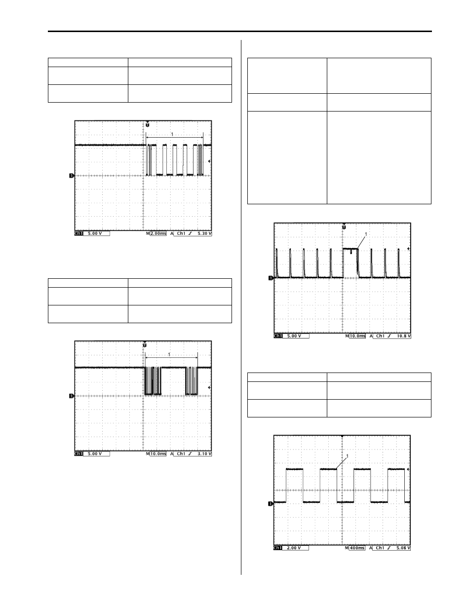
Measurement terminal Rear wiper LOW signal:
CH1: “G30-6” to “G30-12”
Rear wiper INT signal:
CH1: “G30-7” to “G30-12”
Oscilloscope setting
CH1: 5 V/DIV
TIME: 10 ms/DIV
Measurement condition Rear wiper LOW signal:
• Ignition switch is at ON
position, rear wiper switch is
at any position other than
LOW position
Rear wiper INT signal:
• Ignition switch is at ON
position, rear wiper switch is
at any position other than
INT position
Measurement terminal CH1: “G30-19” to “G30-12”
Oscilloscope setting
CH1: 2 V/DIV
TIME: 400 ms/ DIV
Measurement condition Ignition switch is at ON
position
I5JB0AA20015-01
I5JB0AA20016-01
10B-35 Body Electrical Control System:
Reference waveform No. 5
Vehicle speed pulse output signal (1)
Reference waveform No. 6
CAN communication signal
Reference waveform No. 7
Brake fluid level, parking brake or driver seat belt switch
signal (1)
Measurement terminal CH1: “G30-22” to “G30-12”
Oscilloscope setting
CH1: 5 V / DIV
TIME: 200 ms / DIV
Measurement condition Vehicle speed at 10 km/h (6
mph)
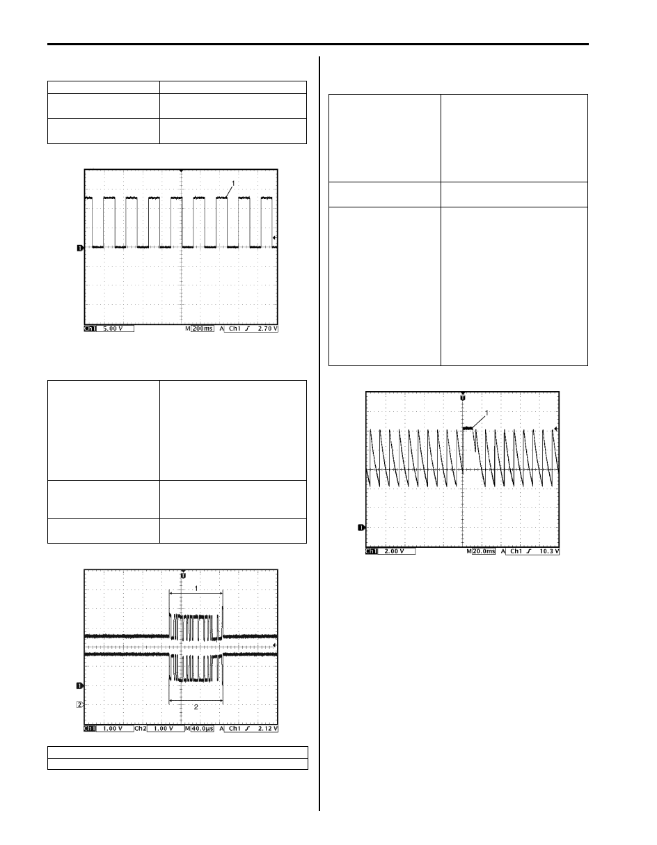
Measurement terminal CAN communication signal for
each control module
CH1: “G31-1” to “G30-12”
CH2: “G31-3” to “G30-12”
CAN communication signal for
DLC
CH1: “G31-2” to “G30-12”
CH2: “G31-4” to “G30-12”
Oscilloscope setting
CH1: 1 V / DIV
CH2: 1 V / DIV
TIME: 40
µs / DIV
Measurement condition Ignition switch is at ON
position
1. CAN communication line signal (High)
2. CAN communication line signal (Low)
I5JB0AA20017-01
I5JB0AA20018-01
Measurement terminal Brake fluid level switch signal:
CH1: “G31-7” to “G30-12”
Parking brake switch signal:
CH1: “G31-8” to “G30-12”
Driver side seat belt switch
signal:
CH1: “G31-40” to “G30-12”
Oscilloscope setting
CH1: 2 V / DIV
TIME: 20 ms / DIV
Measurement condition Brake fluid level switch:
• Ignition switch is at ON
position and brake fluid level
is at specified level
Parking brake switch:
• Ignition switch is at ON
position and parking brake
lever is released.
Driver side seat belt switch:
• Ignition switch is at ON
position and driver seat belt
is fastened
I5JB0AA20019-01
Body Electrical Control System: 10B-36
Reference waveform No. 8
Oil pressure switch signal (1)
Reference waveform No. 9
Keyless entry receiver signal (1)
Repair Instructions
BCM Removal and Installation
S6JB0BA206001
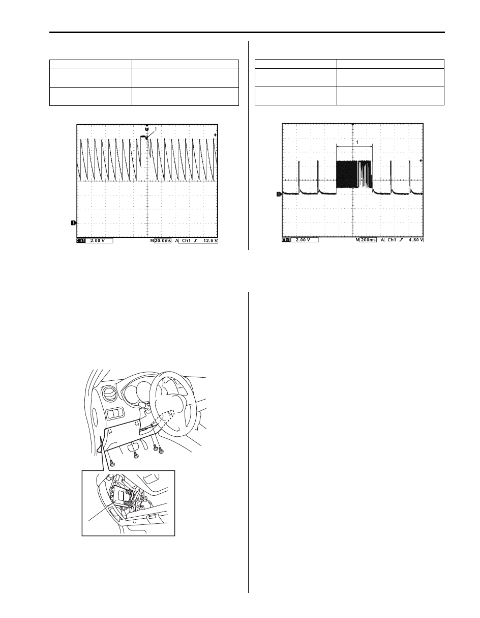
Removal
1) Disconnect negative cable from battery.
2) Remove steering column hole cover (1).
3) Disconnect connectors from BCM.
4) Remove BCM (2).
Installation
Reverse removal procedure for installation, noting
following point.
• Connect connectors securely until it clicks.
Outside Air Temperature Sensor Removal and
Installation
S6JB0BA206002
For removal and installation, refer to “Outside Air
Temperature Sensor Removal and Installation (If
Equipped) in Section 9C”.
Outside Air Temperature Sensor Inspection
S6JB0BA206003
For inspection, refer to “Outside Air Temperature Sensor
Inspection (If Equipped) in Section 9C”.
Measurement terminal CH1: “G31-9” to “G30-12”
Oscilloscope setting
CH1: 2 V / DIV
TIME: 20 ms / DIV
Measurement condition Engine is running and oil
pressure is in normal condition
I5JB0AA20020-01
Measurement terminal CH1: “G31-19” to “G30-12”
Oscilloscope setting
CH1: 2 V / DIV
TIME: 200 ms / DIV
Measurement condition Lock or unlock button of key
less entry transmitter is pushed
I5JB0AA20021-01
1
2
I5JB0AA20022-01
Нет комментариевНе стесняйтесь поделиться с нами вашим ценным мнением.
Текст