Suzuki Grand Vitara JB627. Manual — part 100
1E-4 Engine Lubrication System:
Oil Pan and Oil Pump Strainer Removal and
Installation
S6JB0B1506002
Removal
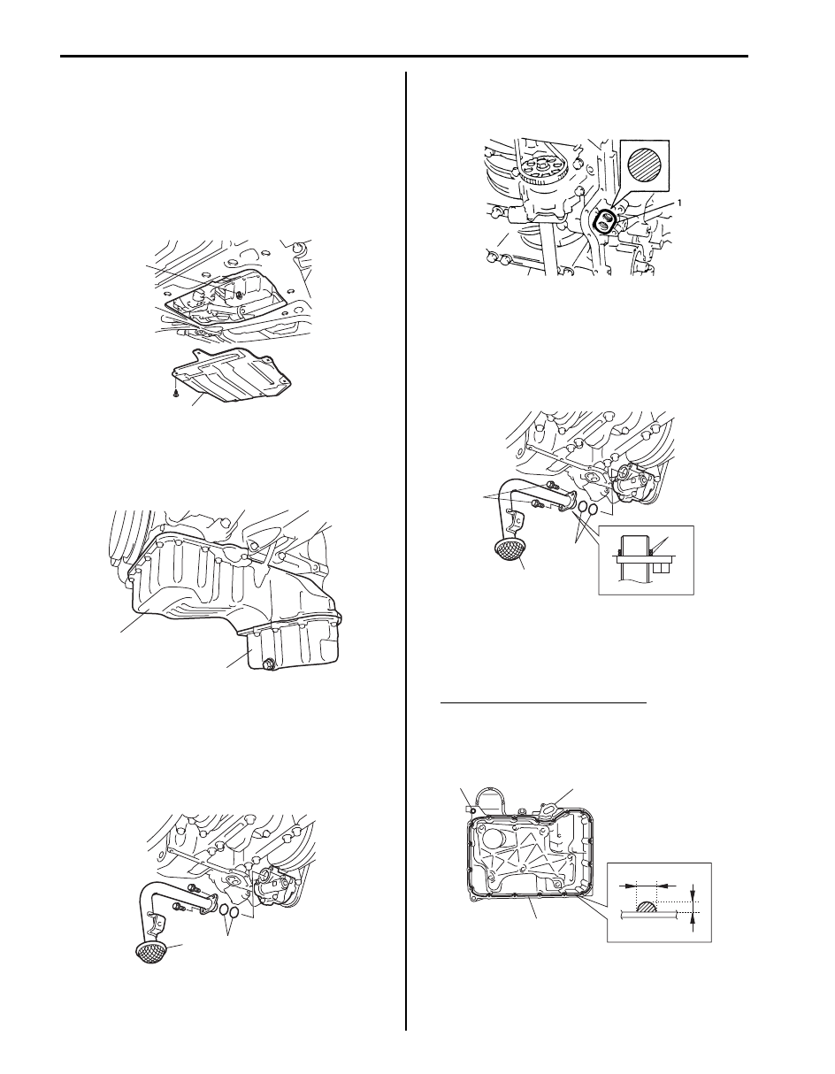
1) Remove oil level gauge guide.
2) Raise vehicle.
3) Remove engine under cover (1).
4) Drain engine oil by removing drain plug (2).
5) Remove front suspension frame referring to “Front
Suspension Frame, Stabilizer Bar and/or Bushings
Removal and Installation in Section 2B”.
6) Remove lower oil pan (2) from upper oil pan (1).
7) Remove drive plate cover (A/T) or clutch housing
lower plate (M/T) from transmission.
8) Remove oil pump strainer bracket.
9) Remove upper oil pan from lower crankcase.
10) Remove oil pump strainer (1) and O-rings (2) from oil
pump.
Installation
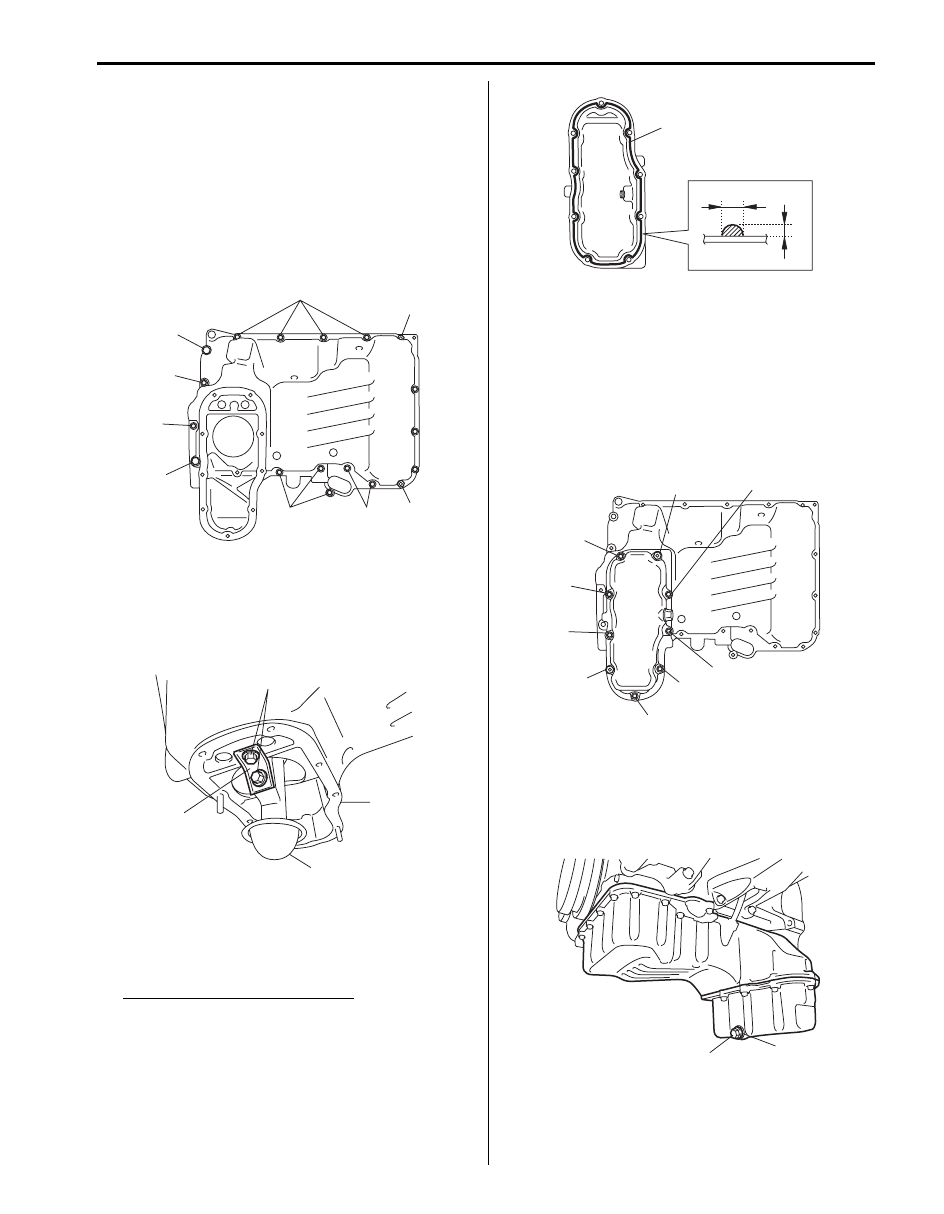
1) Install new O-ring (1) to lower crankcase as shown in
figure.
2) Install new O-rings (2) to oil pump strainer (1)
securely as shown in figure.
Tighten strainer bolts to specified torque.
Tightening torque
Oil pump strainer bolt (a): 11 N·m (1.1 kgf-m, 8.0
lb-ft)
3) Apply sealant “A” to upper oil pan (1) sealing surface
area as shown in figure.
“A”: Sealant 99000–31260 (SUZUKI Bond
No.1217G)
Sealant amount for upper oil pan
Width “a”: 3 mm (0.12 in.)
Height “b”: 2 mm (0.08 in.)
4) Install dowel pin (2) to upper oil pan.
1
2
I6JB01150006-01
1
2
I6JB01150007-01
1
2
I6JB01150008-01
IYSQ01153005-01
2
2
1
(a)
I6JB01150009-01
1
“a”
“A”
“b”
2
I6JB01150010-03
Engine Lubrication System: 1E-5
5) After fitting upper oil pan (1) to lower crankcase, run
in securing bolts and start tightening at the center:
move wrench outward, tightening one bolt at a time.
Tighten bolts and nuts to specified torque.
Tightening torque
Upper oil pan bolt (M6) (a): 11 N·m (1.1 kgf-m,
8.0 lb-ft)
Upper oil pan bolt (M8) (b): 25 N·m (2.5 kgf-m,
19.5 lb-ft)
Upper oil pan nut (c): 11 N·m (1.1 kgf-m, 8.0 lb-ft)
6) Install bracket (3) to oil pump strainer (2) and upper
oil pan (1).
Tightening torque
Oil pump strainer bracket bolt (a): 11 N·m (1.1
kgf-m, 8.0 lb-ft)
7) Apply sealant “A” to lower oil pan sealing surface
area as shown in figure.
“A”: Sealant 99000–31260 (SUZUKI Bond
No.1217G)
Sealant amount for lower oil pan
Width “a”: 3 mm (0.12 in.)
Height “b”: 2 mm (0.08 in.)
8) After fitting lower oil pan to upper oil pan, run in
securing bolts and start tightening at the center:
move wrench outward, tightening one bolt at a time.
Tighten bolts and nuts to specified torque.
Tightening torque
Lower oil pan bolt (a): 11 N·m (1.1 kgf-m, 8.0 lb-
ft)
Lower oil pan nut (b): 11 N·m (1.1 kgf-m, 8.0 lb-
ft)
9) Install new gasket (1) and drain plug (2) to oil pan
after applying engine oil.
Tightening torque
Engine oil drain plug (f): 35 N·m (3.5 kgf-m, 25.5
lb-ft)
(a)
(b)
(c)
(a)
(a)
(a)
(a)
(b)
(c)
I6JB01150011-01
1
2
3
(a)
I6JB01150012-01
“a”
“A”
“b”
I6JB01150013-01
(a)
(b)
(a)
(a)
(a)
(a)
(a)
(a)
(b)
I6JB01150014-01
1
2, (f)
I6JB01150015-01
1E-6 Engine Lubrication System:
10) Install drive plate cover (A/T) or clutch housing lower
plate (M/T) to transmission.
Tightening torque
Drive plate cover (A/T) bolt or clutch housing
lower plate (M/T) bolt (a): 11 N·m (1.1 kgf-m, 8.0
lb-ft)
11) Install front suspension frame referring to “Front
Suspension Frame, Stabilizer Bar and/or Bushings
Removal and Installation in Section 2B”.
12) Install engine under cover.
13) Install oil level gauge guide with new O-ring.
Tightening torque
Oil level gauge guide bolt: 11 N·m (1.1 kgf-m, 8.0
lb-ft)
14) Refill engine with engine oil referring to “Engine Oil
and Filter Change in Section 0B”.
Oil Pan and Oil Pump Strainer Cleaning
S6JB0B1506003
• Inside of oil pans and oil pump strainer screen.
• Clean sealing surface on upper oil pan, lower oil pan
and lower crankcase.
Remove oil, old sealant and dust from sealing
surface.
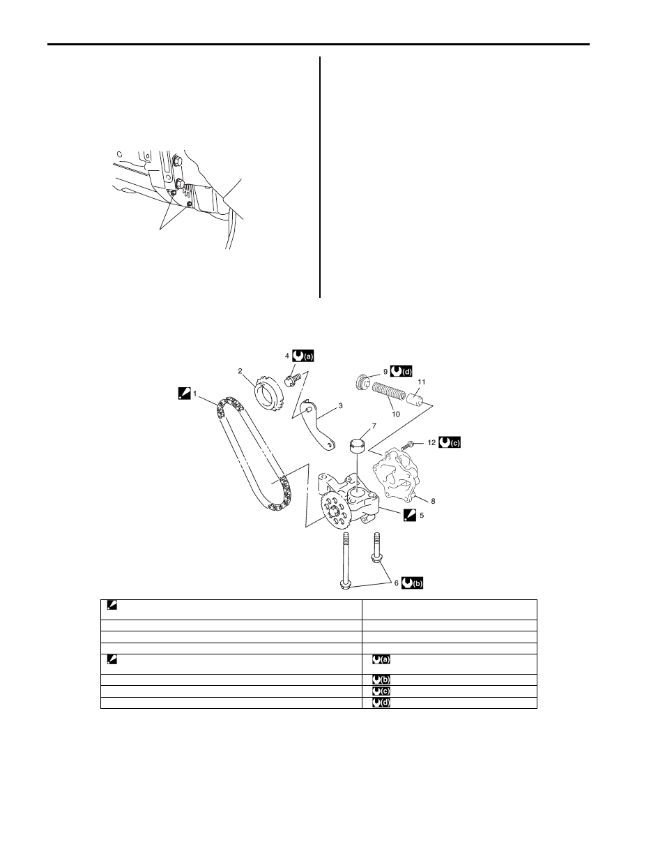
Oil Pump and Oil Pump Chain Components
S6JB0B1506004
(a)
I6JB01150020-01
I6JB01150019-02
1. Oil pump chain:
Install oil pump chain and adjust its tension by the specified procedure
9. Retainer
2. Oil pump drive sprocket
10. Relief spring
3. Oil pump chain guide
11. Relief valve
4. Oil pump chain guide bolt
12. Oil pump bolt
5. Oil pump case No.1
: Do not disassemble.
: 11 N
⋅m (1.1 kgf-m, 8.0 lb-ft)
6. Oil pump mounting bolt
: 25 N
⋅m (2.5 kgf-m, 18.0 lb-ft)
7. Pin
: 12 N
⋅m (1.2 kgf-m, 9.0 lb-ft)
8. Oil pump case No. 2
: 29 N
⋅m (2.9 kgf-m, 21.0 lb-ft)
Engine Lubrication System: 1E-7
Oil Pump and Oil Pump Chain Removal and
Installation
S6JB0B1506005
Removal
1) Remove engine assembly from vehicle referring to
“Engine Assembly Removal and Installation in
Section 1D”.
2) Remove timing chain cover. Refer to “Timing Chain
Cover Removal and Installation in Section 1D”.
3) Remove LH bank 2nd timing chain. Refer to “LH
(No.1) Bank 2nd Timing Chain and Chain Tensioner
Removal and Installation in Section 1D”.
4) Remove 1st timing chain. Refer to “1st Timing Chain
and Chain Tensioner Removal and Installation in
Section 1D”.
5) Remove oil pump chain guide.
6) Remove oil pump mounting bolts.
7) Remove oil pump drive sprocket, oil pump chain and
oil pump all together.
Installation
1) Install oil pump drive sprocket (2), oil pump chain
with oil pump to engine assembly. Tighten oil pump
mounting bolts to specified torque.
Tightening torque
Oil pump mounting bolt (a): 25 N·m (2.5 kgf-m,
18.0 lb-ft)
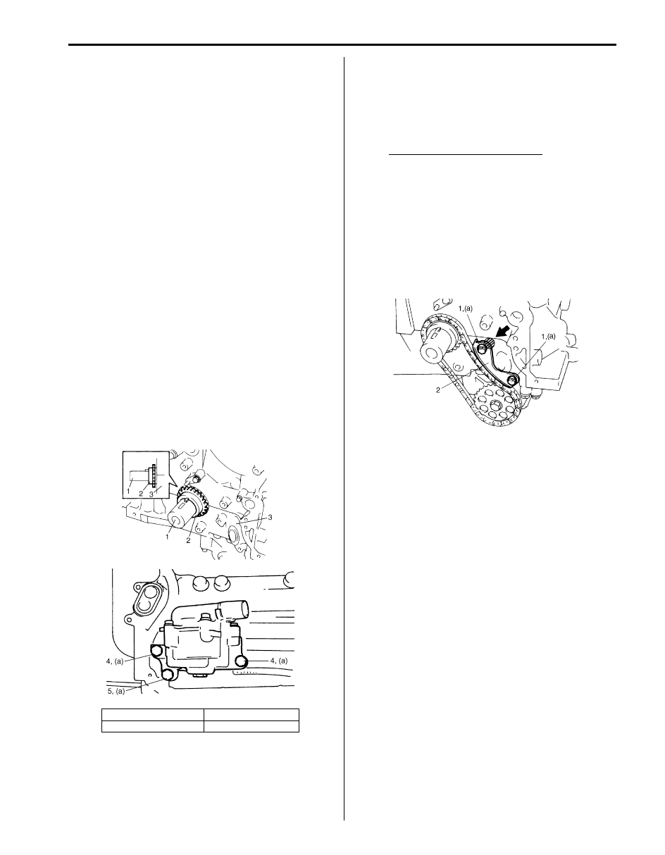
2) Install oil pump chain guide (2), and adjust oil pump
chain tension as follows:
a) Install oil pump chain guide (1) and hand-tighten
oil pump chain guide bolts.
b) Insert specified thickness gauge between center
of oil pump chain guide and chain.
Thickness gauge specification
Thickness: 1.35 mm (0.053 in.)
Width: 14 mm (0.55 in.)
c) Press hatched part of chain guide (2) to 40 N
⋅m
(4.0 kgf-m, 29.0 lb-ft) in arrow direction.
d) Tighten oil pump chain guide bolts (1) to
specified torque while pressing.
Tightening torque
Oil pump chain guide bolt (a): 11 N·m (1.1
kgf-m, 8.0 lb-ft)
e) Remove thickness gauge.
3) Install 1st timing chain. Refer to “1st Timing Chain
and Chain Tensioner Removal and Installation in
Section 1D”.
4) Install LH bank 2nd timing chain. Refer to “LH (No.1)
Bank 2nd Timing Chain and Chain Tensioner
Removal and Installation in Section 1D”.
5) Install timing chain cover. Refer to “Timing Chain
Cover Removal and Installation in Section 1D”.
6) Install oil pans referring to “Oil Pan and Oil Pump
Strainer Removal and Installation”.
7) Install cylinder head covers referring to “Cylinder
Head Covers Removal and Installation in Section
1D”.
8) Install intake manifold, intake collector and electric
throttle body assembly referring to “Intake Collector
and Intake Manifold Removal and Installation in
Section 1D” and “Electric Throttle Body Assembly
Removal and Installation in Section 1D”.
9) Install engine assembly to vehicle referring to
“Engine Assembly Removal and Installation in
Section 1D”.
1. Crankshaft
4. Short bolt
3. Lower crankcase
5. Long bolt
I6JB01150017-01
I4JA01150007-01
Нет комментариевНе стесняйтесь поделиться с нами вашим ценным мнением.
Текст