Suzuki Grand Vitara JB627. Manual — part 101

1E-8 Engine Lubrication System:
Oil Pump and Oil Pump Chain Inspection
S6JB0B1506006
Oil Pump Chain Guide
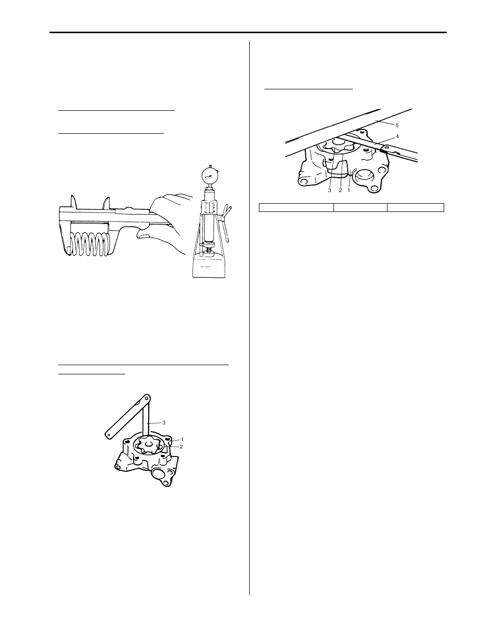
Check shoe (1) for wear or damage.
Oil Pump Drive Sprocket
Check teeth of sprocket for wear or damage.
Oil Pump Sprocket
Check teeth of sprocket for wear or damage.
Oil Pump Chain
Check oil pump chain for wear or damage.
Oil Pump Disassembly and Reassembly
S6JB0B1506007
Disassembly
Disassemble oil pump referring to “Oil Pump and Oil
Pump Chain Components”.
CAUTION
!
Do not remove oil pump sprocket or bolt.
Otherwise, oil pump sprocket and/or oil
pump rotor shaft might be damaged.
Reassembly
1) Wash, clean and then dry all disassembled parts.
2) Apply thin coat of engine oil to inner and outer rotors,
and inside surfaces of oil pump case.
3) Reassemble oil pump. After reassembling oil pump,
check to be sure that rotor turns smoothly by hand.
Tightening torque
Oil pump bolt (a): 12 N·m (1.2 kgf-m, 9.0 lb-ft)
IYSQ01153026-01
IYSQ01153027-01
IYSQ01153028-01
IYSQ01153029-01
IYSQ01153019-01
Engine Lubrication System: 1E-9
Oil Pump Inspection
S6JB0B1506008
• Check outer rotor, inner rotor and oil pump cases for
excessive wear or damage.
• Check relief valve for excessive wear or damage.
• Measure free length and tension of oil relief spring.
Spring (for oil pump) free length
63.47 mm (2.49 in.)
Spring (for oil pump) preload
80.38 – 88.22 N (8.04 – 8.82 kg, 58.14 – 63.80 lb) for
52.0 mm (2.05 in.)
• Radial clearance
Measure clearance of oil pump rotor and oil pump
case using thickness gauge.
Check radial clearance between outer rotor (2) and
case (1), using thickness gauge (3).
If clearance exceeds its limit, replace oil pump
assembly.
Radial clearance between oil pump outer rotor
and oil pump case
Limit: 0.19 mm (0.0075 in.)
• Side clearance
Using straightedge (5) and thickness gauge (4),
measure side clearance. If clearance exceeds its limit,
replace oil pump assembly.
Oil pump side clearance
Limit: 0.11 mm (0.0043 in.)
IYSQ01141105-01
IYSQ01153020-01
1. Oil pump case No.1
2. Outer rotor
3. Inner rotor
IYSQ01153021-01
1E-10 Engine Lubrication System:
Specifications
Tightening Torque Specifications
S6JB0B1507001
NOTE
The specified tightening torque is also described in the following.
“Oil Pan and Oil Pump Strainer Components”
“Oil Pump and Oil Pump Chain Components”
Reference:
For the tightening torque of fastener not specified in this section, refer to “Fastener Information in Section 0A”.
Special Tools and Equipment
Recommended Service Material
S6JB0B1508001
NOTE
Required service material is also described in the following.
“Oil Pan and Oil Pump Strainer Components”
Special Tool
S6JB0B1508002
Fastening part
Tightening torque
Note
N
⋅m
kgf-m
lb-ft
Oil pressure switch
13
1.3
9.5
Oil pump strainer bolt
11
1.1
8.0
Upper oil pan bolt (M6)
11
1.1
8.0
Upper oil pan bolt (M8)
25
2.5
19.5
Upper oil pan nut
11
1.1
8.0
Oil pump strainer bracket bolt
11
1.1
8.0
Lower oil pan bolt
11
1.1
8.0
Lower oil pan nut
11
1.1
8.0
Engine oil drain plug
35
3.5
25.5
Drive plate cover (A/T) bolt or clutch housing
lower plate (M/T) bolt
11
1.1 8.0
Oil level gauge guide bolt
11
1.1
8.0
Oil pump mounting bolt
25
2.5
18.0
Oil pump chain guide bolt
11
1.1
8.0
Oil pump bolt
12
1.2
9.0
Material
SUZUKI recommended product or Specification
Note
Sealant
SUZUKI Bond No.1217G
P/No.: 99000–31260
09915–76510
09915–77311
Oil pressure gauge
attachment
Oil pressure gauge
Engine Cooling System: 1F-1
Engine
Engine Cooling System
General Description
Cooling System Description
S6JB0B1601001
The cooling system consists of the radiator cap, radiator,
coolant reservoir, hoses, water pump, cooling fan and
thermostat. The radiator is of tube-and-fin type.
Coolant Description
S6JB0B1601002
WARNING
!
• Do not remove radiator cap to check
engine coolant level; check coolant
visually at the see-through coolant
reservoir. Coolant should be added only to
reservoir as necessary.
• As long as there is pressure in the cooling
system, the temperature can be
considerably higher than the boiling
temperature of the solution in the radiator
without causing the solution to boil.
Removal of the radiator cap while engine is
hot and pressure is high will cause the
solution to boil instantaneously and
possibly with explosive force, spewing the
solution over engine, fenders and person
removing cap. If the solution contains
flammable anti-freeze such as alcohol (not
recommended for use at any time), there is
also the possibility of causing a serious
fire.
• Check to make sure that engine coolant
temperature is cold before removing any
part of cooling system.
• Also be sure to disconnect negative (–)
cable from battery terminal before
removing any part.
The coolant recovery system is standard. The coolant in
the radiator expands with heat, and the coolant is
overflowed to the reservoir.
When the system cools down, the coolant is drawn back
into the radiator.
The cooling system has been filled with a quality coolant
that is a 50/50 mixture of water and ethylene glycol
antifreeze.
This 50/50 mixture coolant solution provides freezing
protection to –36
°C (–33 °F).
• Maintain cooling system freeze protection at –36
°C (–
33
°F) to ensure protection against corrosion and loss
of coolant from boiling. This should be done even if
freezing temperatures are not expected.
• Add ethylene glycol base coolant when coolant has to
be added because of coolant loss or to provide added
protection against freezing at temperature lower than
–36
°C (–33 °F).
NOTE
• Alcohol or methanol base coolant or plain
water alone should not be used in cooling
system at any time as damage to cooling
system could occur.
• Coolant must be mixed with deminerated
water or distilled water.
Anti-freeze proportioning table
Coolant capacity
Engine, radiator and heater: 7.4 liters (15.64/13.03
US/lmp pt.)
Reservoir: 0.8 liters (1.69/1.41 US/lmp pt.)
Total: 8.2 liters (17.49/14.43 US/lmp pt.)
Freezing temperature
°C
–36
°F
–33
Anti-freeze / Anti-corrosion
coolant concentration
%
50
Ratio of compound to cooling
water
ltr.
4.1/4.1
US pt.
8.75/8.75
Imp pt.
7.22/7.22
Нет комментариевНе стесняйтесь поделиться с нами вашим ценным мнением.
Текст