Suzuki Grand Vitara JB627. Manual — part 48

1A-141 Engine General Information and Diagnosis:
DTC Troubleshooting
NOTE
Before this trouble shooting is performed, read the precautions for DTC troubleshooting referring to
“Precautions for DTC Troubleshooting”.
Step
Action
Yes
No
1
Was “Engine and Emission Control System Check”
performed?
Go to Step 2.
Go to “Engine and
Emission Control
System Check”.
2
A/C compressor relay signal check
1) Connect scan tool to DLC with ignition switch turned
OFF.
2) Start engine and then operate A/C system.
3) Check A/C compressor relay control signal of “A/C
Comp Relay” under “Data List” displayed on scan tool.
• A/C switch is at ON position and blower selector is
other than OFF position: “ON”.
• A/C switch is at OFF position and blower selector is at
OFF position: “OFF”.
Does “A/C Comp Relay” signal correctly?
Intermittent trouble.
Check for intermittent
referring to “Intermittent
and Poor Connection
Inspection in Section
00”.
Go to Step 3.
3
A/C compressor relay control signal check
1) Disconnect connectors from ECM with ignition switch
turned OFF.
2) Check that A/C compressor relay control signal circuit
voltage between ECM connector and vehicle body
ground.
• Ignition switch is at “ON” position: 10 – 14 V
• Ignition switch is at “OFF” position: 0 – 1 V
Is it in good condition?
Substitute a known
good ECM and recheck.
Go to Step 4.
4
A/C compressor relay power supply voltage check
1) Turn ignition switch to OFF position.
2) Remove A/C compressor relay.
3) Check that A/C compressor relay power supply voltage
between A/C compressor relay connector and vehicle
body ground.
• Ignition switch is at “ON” position: 10 – 14 V
• Ignition switch is at “OFF” position: 0 – 1 V
Is it in good condition?
Go to Step 5.
Repair or replace power
supply circuit of A/C
compressor relay.
5
A/C compressor relay check
Check A/C compressor relay for operation referring to “A/C
Compressor Relay Inspection in Section 7B”.
Is it in good condition?
Control signal circuit of
A/C compressor relay is
open or short. If circuit is
OK, substitute a known
good ECM and recheck.
Replace A/C
compressor relay.
Engine General Information and Diagnosis: 1A-142
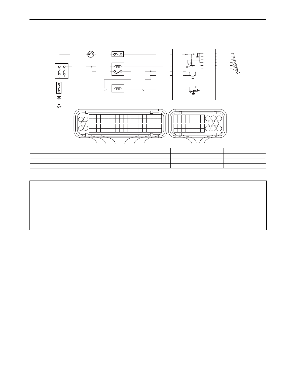
DTC P0661 / P0662: Intake Manifold Tuning Valve Control Circuit Low / High
S6JB0B1104054
Wiring Diagram
DTC Detecting Condition and Trouble Area
DTC Confirmation Procedure
1) With ignition switch turned OFF, connect scan tool.
2) Turn ON ignition switch and clear DTC by using scan tool if any.
3) Start engine and run it for 10 seconds.
4) Check DTC by using scan tool.
BLU/BLK
BLU/BLK
BLU/BLK
BLU/BLK
GRY/RED
BLK/RED
BLK/RED
BLK/RED
BLU
12V 5V
E23-8
E23-16
E23-2
E23-3
C37-29
WHT/GRN
C37-59
C37-58
C37-39
C37-73
C37-80
BLK/YEL
BLK/ORN
BLK/ORN
BLK/YEL
BLK/YEL
1
3 2
4
5
6
7
8
9
1110
12
13
14
15
16
17
18
19
20
17
18
19
20
21
22
23
24
25
26
27
28
29
30
31
33
34
35
36
37
38
39
40
32
1
2
3
4
5
6
7
8
9
10
11
12
13
14
15
16
21
22
23
24
25
26
27
28
29
30
31
32
33
34
35
36
37
38
39
40
41
42
43
44
45
46
47
48
49
50
51
52
53
54
55
56
57
58
59
60
61
62
63
64
65
66
67
68
69
70
71
72
73
74
75
76
77
78
79
80
81
E23
C37
BLK/ORN
C37-81
BLK/YEL
BLK/WHT
4
8
7
5
3
2
1
P
C
6
I6JB01110048-03
P: IMT vacuum solenoid valve power supply circuit
3. “IG COIL” fuse
7. “FI” fuse
C: IMT vacuum solenoid valve control circuit
4. Fuse box No.2
8. “IGN” fuse
1. IMT vacuum solenoid valve
5. Ignition switch
2. Main relay
6. ECM
DTC detecting condition
Trouble area
DTC P0661: Intake Manifold Turning Valve Control Circuit Low
Circuit voltage of intake manifold tuning vacuum solenoid valve is less
than specification even if it solenoid valve is turned OFF.
(1 driving cycle detection logic but MIL does not light up)
• IMT vacuum solenoid valve and its circuit
• ECM
DTC P0662: Intake Manifold Turning Valve Control Circuit High
Circuit voltage of intake manifold tuning vacuum solenoid valve is more
than specification even if it solenoid valve is turned ON.
(1 driving cycle detection logic but MIL does not light up)

1A-143 Engine General Information and Diagnosis:
DTC Troubleshooting
NOTE
Before this trouble shooting is performed, read the precautions for DTC troubleshooting referring to
“Precautions for DTC Troubleshooting”.
Step
Action
Yes
No
1
Was “Engine and Emission Control System Check”
performed?
Go to Step 2.
Go to “Engine and
Emission Control
System Check”.
2
IMT vacuum solenoid valve power supply voltage check
1) Disconnect connector from IMT vacuum solenoid valve
with ignition switch turned OFF.
2) Check for proper terminal connection to IMT vacuum
solenoid valve and ECM connectors.
3) If connections are OK, check that IMT vacuum solenoid
valve power supply voltage is battery voltage between
IMT vacuum solenoid valve connector and vehicle body
ground with ignition switch turned ON.
Is it in good condition?
Go to Step 3.
Repair or replace IMT
vacuum solenoid valve
power supply circuit.
3
Wire harness check
1) Disconnect connectors from ECM with ignition switch
turned OFF.
2) Check that IMT vacuum solenoid valve circuit is as
follows.
• Wiring harness resistance of IMT vacuum solenoid
valve control circuit is less than 3
Ω.
• Insulation resistance of IMT vacuum solenoid valve
control circuit is infinity between IMT vacuum solenoid
valve connector and vehicle body ground.
• Insulation resistance of wire harness is infinity
between IMT vacuum solenoid valve control terminal
and each other terminal at IMT vacuum solenoid valve
connector.
• Circuit voltage of IMT vacuum solenoid valve control
circuit is 0 – 1 V with ignition switch turned ON.
Are they in good condition?
Go to Step 4.
Repair or replace IMT
vacuum solenoid valve
control circuit.
4
IMT vacuum solenoid valve check
1) Check IMT vacuum solenoid valve for coil resistance
referring to “IMT Vacuum Tank Assembly Inspection in
Section 1C”.
Is it in “good condition”?
Substitute a known
good ECM and recheck.
Replace IMT vacuum
solenoid valve.
Engine General Information and Diagnosis: 1A-144
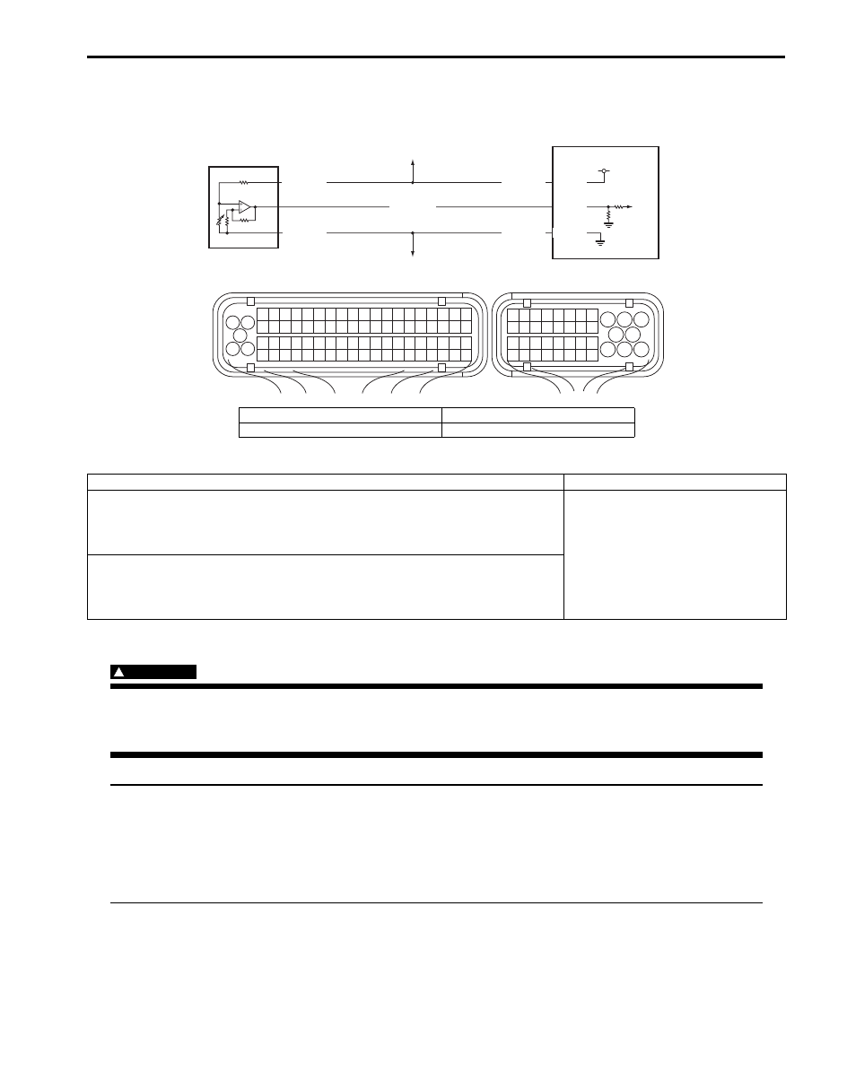
DTC P1107 / P1108: Manifold Absolute Pressure Sensor Rationality Check - Low / High
S6JB0B1104055
Wiring Diagram
DTC Detecting Condition and Trouble Area
DTC Confirmation Procedure
WARNING
!
• When performing a road test, select a place where there is no traffic or possibility of a traffic
accident and very careful during testing to avoid occurrence of an accident.
• Road test should be carried out with 2 persons, a driver and a tester, on a level road.
NOTE
Check to make sure that the following conditions are satisfied when using this “DTC Confirmation
Procedure”.
• Intake air temperature: –10
°C (14 °F) or higher
• Engine coolant temperature: higher than 45
°C (113 °F)
• The following DTC(s) are not detected: MAF sensor, ECT sensor and MAP sensor (other than P1107
and P1108)
1) With ignition switch OFF, connect scan tool.
2) Turn ON ignition switch and clear DTC by using scan tool if any.
3) Start engine and warm up to normal operating temperature.
4) Increase vehicle speed to 35 mph (56 km/h) for 30 sec.
5) Stop vehicle and check DTC and pending DTC by using scan tool.
1
3 2
4
5
6
7
8
9
1110
12
13
14
15
16
17
18
19
20
17
18
19
20
21
22
23
24
25
26
27
28
29
30
31
33
34
35
36
37
38
39
40
32
1
2
3
4
5
6
7
8
9
10
11
12
13
14
15
16
21
22
23
24
25
26
27
28
29
30
31
32
33
34
35
36
37
38
39
40
41
42
43
44
45
46
47
48
49
50
51
52
53
54
55
56
57
58
59
60
61
62
63
64
65
66
67
68
69
70
71
72
73
74
75
76
77
78
79
80
81
E23
C37
4
1
2
3
GRY/RED
5V
C37-49
C37-68
RED/WHT
GRY/GRN
GRY/RED
GRY/GRN
C37-67
I6JB01110049-03
1. MAP sensor
3. To other sensors
2. To other sensors
4. ECM
DTC detecting condition
Trouble area
DTC P1107: Manifold Absolute Pressure Sensor Rationality Check - Low
Input voltage of MAP sensor circuit is lower than the 1 V even though vehicle
runs under engine load factor of 43% or more.
(2 driving cycle detection logic)
• MAP sensor and its circuit
• ECM
DTC P1108: Manifold Absolute Pressure Sensor Rationality Check - High
Input voltage of MAP sensor circuit is more than the specified 2.7 V even though
vehicle runs under engine load factor of 27% or less.
(2 driving cycle detection logic)
Нет комментариевНе стесняйтесь поделиться с нами вашим ценным мнением.
Текст