Suzuki Grand Vitara JB627. Manual — part 47

1A-137 Engine General Information and Diagnosis:
DTC Confirmation Procedure
1) With ignition switch turned OFF, connect scan tool.
2) Turn ON ignition switch and clear DTC by using scan tool if any.
3) Check DTC by using scan tool.
DTC Troubleshooting
NOTE
• Before this trouble shooting is performed, read the precautions for DTC troubleshooting referring to
“Precautions for DTC Troubleshooting”.
• When DTC P0107 is indicated together, it is possible that sensor power supply circuit is open.
• When DTC P0108 is indicated together, it is possible that sensor power supply circuit is shorted to
power circuit and/or sensor ground circuit is open.
DTC P0601 / P0602 / P0607: Internal Control Module Memory Check Sum Error / Control Module
Programming Error / Control Module Performance
S6JB0B1104051
System Description
Internal control module is installed in ECM.
NOTE
After reprogramming of ECM is executed, if the DTC P0601 and/or P0602 are indicated, it is possible
that the reprogramming of ECM is not completed correctly.
DTC Detecting Condition and Trouble Area
DTC Confirmation Procedure
1) With ignition switch OFF, connect scan tool.
2) Turn ON ignition switch and clear DTC by using scan tool if any.
3) Start engine and run it at idle if possible.
4) Check DTC by using scan tool.
Step
Action
Yes
No
1
Was “Engine and Emission Control System Check”
performed?
Go to Step 2.
Go to “Engine and
Emission Control
System Check”.
2
A/C refrigerant pressure sensor and its circuit check
1) Check A/C refrigerant pressure sensor and its circuit for
condition referring to “A/C Refrigerant Pressure Sensor
and Its Circuit Inspection in Section 7B”.
Is it in good condition?
Substitute a known
good ECM and recheck.
Repair or replace
defective parts.
DTC detecting condition
Trouble area
DTC P0601: Internal Control Module Memory Check Sum
Error
Data write error or check sum error
(1 driving cycle detection logic)
• ECM
DTC P0602: Control Module Programming Error
Data programming error
(1 driving cycle detection logic)
DTC P0607: Control Module Performance
Internal processor error
(1 driving cycle detection logic)

Engine General Information and Diagnosis: 1A-138
DTC Troubleshooting
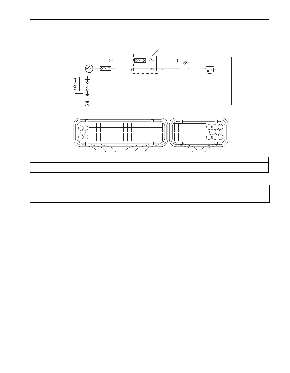
DTC P0616 / P0617: Starter Relay Circuit Low / High
S6JB0B1104052
Wiring Diagram
Circuit Description
Engine start signal is sent from engine starter circuit while engine cranking.
Step
Action
Yes
No
1
DTC recheck
1) Clear DTC referring to “DTC Clearance”
2) Turn off ignition switch.
3) Turn on ignition switch and check DTC.
Is DTC P0601, P0602 or P0607 still indicated?
Go to Step 2.
Intermittent trouble.
Check for intermittent
referring to “Intermittent
and Poor Connection
Inspection in Section
00”.
2
ECM reprogramming check
Was reprogramming of ECM executed?
Execute reprogramming
of ECM correctly once
again.
Go to Step 3.
3
ECM power and ground circuit check
1) Check that ECM power supply circuit and ECM ground
circuit is in good condition referring to “ECM Power and
Ground Circuit Check”.
Are checking results OK?
Substitute a known
good ECM and recheck.
Repair ECM power or
ground circuit.
1
3 2
4
5
6
7
8
9
1110
12
13
14
15
16
17
18
19
20
17
18
19
20
21
22
23
24
25
26
27
28
29
30
31
33
34
35
36
37
38
39
40
32
1
2
3
4
5
6
7
8
9
10
11
12
13
14
15
16
21
22
23
24
25
26
27
28
29
30
31
32
33
34
35
36
37
38
39
40
41
42
43
44
45
46
47
48
49
50
51
52
53
54
55
56
57
58
59
60
61
62
63
64
65
66
67
68
69
70
71
72
73
74
75
76
77
78
79
80
81
E23
C37
1
12
13
14
6
5
7
8
3
2
11
4
15 10
9
C37-59
C37-58
C37-39
C37-73
C37-80
BLK/YEL
BLK/ORN
BLK/ORN
BLK/YEL
BLK/YEL
BLK/ORN
C37-81
12V 5V
BLU/BLK
BLU/BLK
BLK/RED
BLK/RED
BLK/RED
BLU
E23-29
E23-2
E23-3
E23-16
BLK/YEL
BLK/YEL
BLK/YEL
BLK/WHT
BLK/YEL
BLK/YEL
[A]: BLK/RED
WHT/RED
BLK/RED
BLK
BLU/BLK
C37-28
[B]: BLK
WHT/GRN
BLK/YEL
WHT/RED
BLU/BLK
C37-66
BLK/YEL
S
I6JB01110046-03
[A]: For A/T model
3. Ignition switch
8. “ST SIG” fuse
13. CMP sensor
[B]: For M/T model
4. Fuse box No.2
9. “STR MOT” fuse
14. Signal rotor
S: Start signal circuit
5. Transmission range switch (A/T model)
10. “IGN” fuse
15. “FI” fuse
1. ECM
6. Starting motor control relay
11. Starting motor magnet clutch
2. Starter motor
7. “IG CIOL” fuse
12. Main relay

1A-139 Engine General Information and Diagnosis:
DTC Detecting Condition and Trouble Area
DTC Confirmation Procedure
NOTE
Before performing troubleshooting of DTC P0616, make sure that DTC of VSS is not detected.
1) With ignition switch OFF, connect scan tool.
2) Turn ON ignition switch and clear DTC by using scan tool if any.
3) Start engine and run it for 1 minute.
4) Check DTC and pending DTC by using scan tool.
DTC Troubleshooting
NOTE
Before this trouble shooting is performed, read the precautions for DTC troubleshooting referring to
“Precautions for DTC Troubleshooting”.
DTC detecting condition
Trouble area
P0616: Starter Relay Circuit Low
No starter switch signal is inputted for 20 sec. or more even though there is
CMP sensor input with vehicle speed at 2 km/h or less.
(2 driving cycle detection logic)
• Engine start signal circuit
• ECM
P0617: Starter Relay Circuit High
There is starter switch input for 180 sec. or more even though engine operates
at 600 rpm or more.
(2 driving cycle detection logic)
Step
Action
Yes
No
1
Was “Engine and Emission Control System Check”
performed?
Go to Step 2.
Go to “Engine and
Emission Control
System Check”.
2
Engine start signal check
1) Connect scan tool to DLC with ignition switch turned
OFF.
2) Turn ignition switch to ON position.
3) Check engine start signal of “Starter SW” under “Data
List” displayed on scan tool.
• Ignition switch is at “START” position: “ON”.
• Ignition switch is at other than “START” position:
“OFF”.
Does “Starter SW” signal correctly?
Intermittent trouble.
Check for intermittent
referring to “Intermittent
and Poor Connection
Inspection in Section
00”.
Go to Step 3.
3
Engine start signal check
1) Disconnect connectors from ECM with ignition switch
turned OFF.
2) Check that circuit voltage between start signal terminal
of ECM connector and vehicle body ground.
• Ignition switch is at “START” position: 8 – 14 V
• Ignition switch is at other than “START” position: 0 – 1
V
Is it in good condition?
Substitute a known
good ECM and recheck.
Repair or replace start
signal circuit.
Engine General Information and Diagnosis: 1A-140
DTC P0645: A/C Clutch Relay Control Circuit
S6JB0B1104053
Wiring Diagram
DTC Detecting Condition and Trouble Area
DTC Confirmation Procedure
1) With ignition switch turned OFF, connect scan tool.
2) Turn ON ignition switch and clear DTC by using scan tool if any.
3) Start engine and then operate A/C system.
4) Check DTC by using scan tool.
1
3 2
4
5
6
7
8
9
1110
12
13
14
15
16
17
18
19
20
17
18
19
20
21
22
23
24
25
26
27
28
29
30
31
33
34
35
36
37
38
39
40
32
1
2
3
4
5
6
7
8
9
10
11
12
13
14
15
16
21
22
23
24
25
26
27
28
29
30
31
32
33
34
35
36
37
38
39
40
41
42
43
44
45
46
47
48
49
50
51
52
53
54
55
56
57
58
59
60
61
62
63
64
65
66
67
68
69
70
71
72
73
74
75
76
77
78
79
80
81
E23
C37
PNK
WHT/RED
E23-37
YEL/GRN
GRN/WHT
BLK/RED
5
6
4
1
P
C
2
3
I6JB01110047-03
P: A/C compressor relay power supply circuit
2. A/C compressor
5. Ignition switch
C: A/C compressor relay control circuit
3. ECM
6. “IG2 SIG” fuse
1. A/C compressor relay (included in integration relay)
4. “CPRSR” fuse
DTC detecting condition
Trouble area
Monitor signal of A/C compressor relay is different from command signal.
(1 driving cycle detection logic)
• A/C compressor relay and its circuit
• ECM
Нет комментариевНе стесняйтесь поделиться с нами вашим ценным мнением.
Текст