Suzuki Grand Vitara JB627. Manual — part 183
4E-13 ABS:
ABS Warning Light Does Not Come ON at Ignition Switch ON
S6JB0B4504008
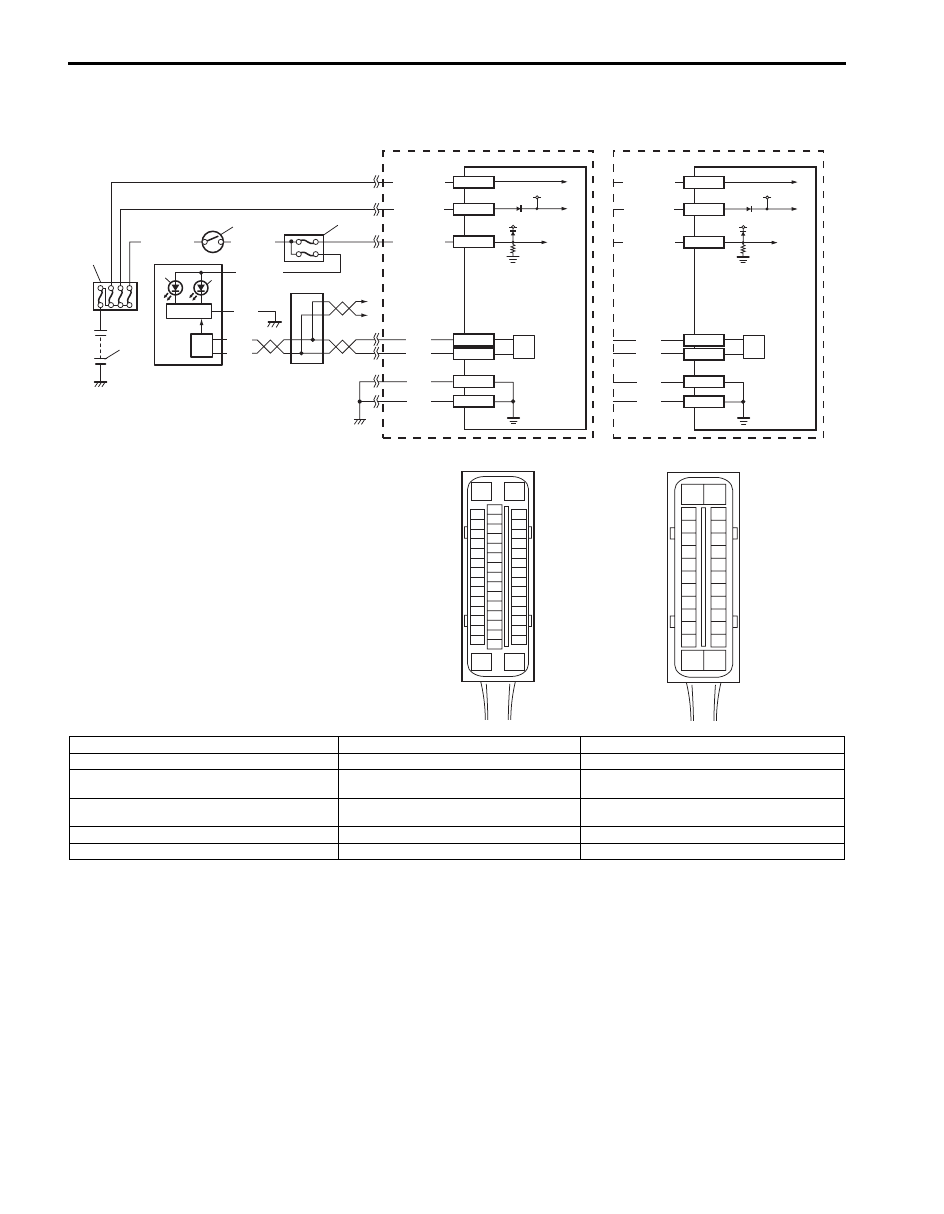
Wiring Diagram
3
4
2
1
[C]
E53-16
E53-47
12V
12V
E53-32
E53-1
E53-35
GRN/ORN
PPL/RED
BLK/YEL
WHT/GRN
WHT/RED
WHT/BLU
BLK
BLK
BLK
RED
WHT
RED
WHT
E53-13
E53-44
11
10
5
7
8
6
9
E53
16
1
15
2
3
4
5
6
7
8
9
10
11
12
13
14
17
18
19
20
21
22
23
24
25
26
27
28
29
30
31
32
33
34
35
36
37
38
39
40
41
42
43
44
45
46
47
E03-13
E03-26
12V
12V
E03-1
E03-14
E03-7
GRN/ORN
WHT/RED
WHT/BLU
BLK
BLK
RED
WHT
E03-12
E03-6
13
9
[D]
E03
15
16
17
18
19
20
21
22
23
24
25
2
3
4
5
6
7
8
9
10
11
12
1
13
14
26
9
12
[A]
[B]
I6JB01450005-01
[A]: ESP
® model
3. Ignition switch
9. CAN driver
[B]: Non-ESP
® model
4. Circuit fuse (in junction block assembly)
10. CAN junction
[C]: ESP
® hydraulic unit / control module connector
(viewed from terminal side)
5. Combination meter
11. To TCM, BCM, 4WD control module, keyless
start control module and steering angle sensor
[D]: ABS hydraulic unit / control module connector
(viewed from terminal side)
6. ABS warning light
12. ESP
® hydraulic unit / control module assembly
1. Battery
7. EBD warning light (Brake warning light)
13. ABS hydraulic unit / control module assembly
2. Main fuse box
8. Light driver module

ABS: 4E-14
Circuit Description
Operation (ON/OFF) of ABS warning light is controlled by ABS (ESP
®) control module through light driver module in
combination meter.
If the antilock brake system is in good condition, ABS (ESP
®) control module turns ABS warning light ON at the
ignition switch ON, keeps it ON for 2 seconds and then turns it OFF. If an abnormality in the system is detected, ABS
warning light is turned ON continuously by ABS (ESP
®) control module. Also, it is turned ON continuously by light
driver module when the connector of ABS (ESP
®) control module is disconnected.
Troubleshooting
Step
Action
Yes
No
1
1) Turn ignition switch to ON position.
Do other warning lights come ON?
Go to Step 2.
Go to Step 3.
2
1) Connect scan tool to DLC with ignition switch turned
OFF.
2) Turn ignition switch to OFF position and check DTC.
Is there DTC U1073?
Go to “DTC U1073:
Control Module
Communication Bus
Off”.
Substitute a known-
good combination meter
and recheck. If ABS
warning light remains
OFF, substitute a
known-good ABS
(ESP
®) hydraulic unit /
control module
assembly and recheck.
3
Is Circuit fuse for combination meter in good condition?
Go to Step 4.
Replace fuse and check
for short circuit to
ground.
4
Check CAN communication circuit between combination
meter and ABS (ESP
®) hydraulic unit / control module
referring to “DTC U1073: Control Module Communication
Bus Off”.
Is CAN communication circuit in good condition?
Go to Step 5.
Repair or replace.
5
1) Remove combination meter with ignition switch turned
OFF.
2) Check for proper connection to “PPL/RED” and “BLK”
wire of combination meter connector.
3) If OK, turn ON ignition switch and measure voltage at
“PPL/RED” wire of combination meter connector and
vehicle body ground.
Is it 10 – 14 V?
Go to Step 6.
Repair power supply
circuit for combination
meter.
6
1) Measure resistance between “BLK” wire of combination
meter connector and vehicle body ground.
Is resistance less than 2
Ω
?
Replace combination
meter.
“BLK” circuit open or
high resistance.

4E-15 ABS:
ABS Warning Light Comes ON Steady
S6JB0B4504009
Wiring Diagram
Refer to “ABS Warning Light Does Not Come ON at Ignition Switch ON”.
Circuit Description
Operation (ON/OFF) of ABS warning light is controlled by ABS (ESP
®) control module through light driver module in
combination meter.
If the Antilock brake system is in good condition, ABS (ESP
®) control module turns ABS warning light ON at the
ignition switch ON, keeps it ON for 2 seconds and then turns it OFF. If an abnormality in the system is detected, ABS
warning light is turned ON continuously by ABS (ESP
®) control module. Also, it is turned ON continuously by light
driver module when the connector of ABS (ESP
®) control module is disconnected.
Troubleshooting
Step
Action
Yes
No
1
1) Perform diagnostic trouble code check.
Is there any DTC(s)?
Go to Step 7 of “ABS
Check”.
Go to Step 2.
2
Are main fuses for ABS pump motor and ABS solenoid in
good condition?
Go to Step 3.
Replace fuse and check
circuit for short to
ground.
3
1) Turn ignition switch to OFF.
2) Disconnect ABS (ESP
®) hydraulic unit / control module
connector.
3) Check for proper connection to ABS (ESP
®) hydraulic
unit / control module connector at terminals “E03-7”,
“E03-13” and “E03-26” (or “E53-16”, “E53-35” and “E53-
47”.)
4) If OK then turn ignition switch to ON position and
measure voltage between terminal “E03-7” (or “E53-35”)
and vehicle body ground.
Is it 10 – 14 V?
Go to Step 4.
“GRN/ORN” circuit
open.
4
1) Turn ignition switch to OFF position.
2) Check for proper connection to ABS (ESP
®) hydraulic
unit / control module connector at terminals “E03-1” and
“E03-14” (or “E53-1”, “E53-32”).
3) If OK then turn ignition switch to ON position and
measure voltage between each terminal of “E03-1”,
“E03-14” (or “E53-1”, “E53-32”) and vehicle body
ground.
Are they 10 – 14 V?
Go to Step 5.
“WHT/RED” and/or
“WHT/BLU” circuit
open.
5
1) Turn ignition switch to OFF and measure resistance
between each terminal of “E03-13”, “E03-26” (or “E53-
16”, “E53-47”) and vehicle body ground.
Is resistance less than 2
Ω
?
Go to Step 6.
Ground circuit for ABS
(ESP
®) hydraulic unit /
control module open or
high resistance.
6
Check CAN communication circuit between combination
meter and ABS (ESP
®) hydraulic unit / control module
referring to “DTC U1073: Control Module Communication
Bus Off”.
Is CAN communication circuit in good condition?
Substitute a known-
good combination meter
and recheck. If ABS
warning light remains
ON, substitute a known-
good ABS (ESP
®)
hydraulic unit / control
module assembly and
recheck.
Repair or replace.
ABS: 4E-16
EBD Warning Light (Brake Warning Light) Comes ON Steady
S6JB0B4504010
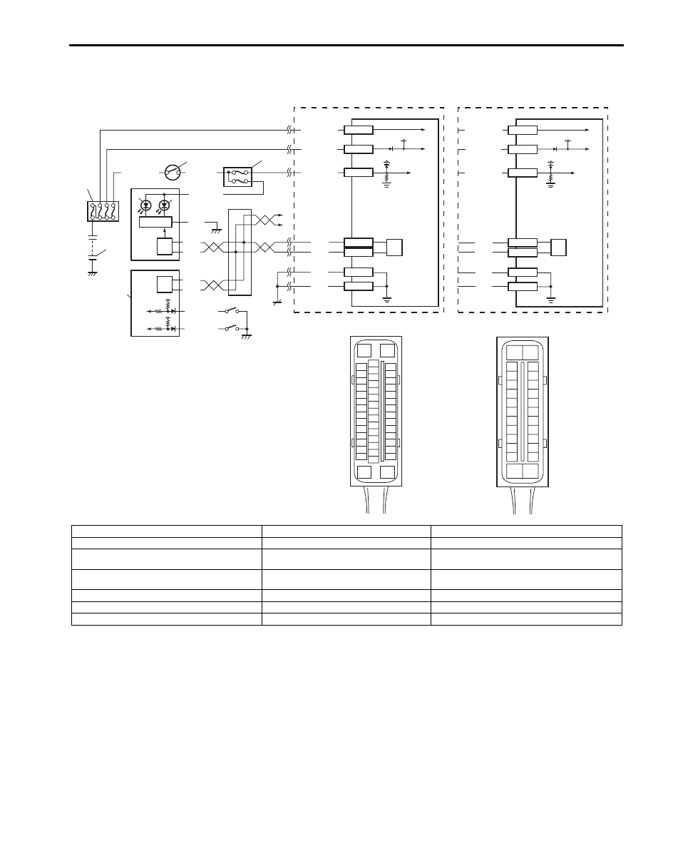
Wiring Diagram
Circuit Description
EBD warning light (brake warning light) is controlled by parking brake switch, brake fluid level switch and ABS (ESP
®)
hydraulic unit / control module assembly through light driver module in combination meter.
EBD warning light turns ON when parking brake switch is ON and/or brake fluid level is lower than minimum level.
The information of parking brake switch and brake fluid level are transmitted from BCM to light driver module in
combination meter through CAN communication line.
3
4
2
1
[C]
E53-16
E53-47
12V
12V
E53-32
E53-1
E53-35
GRN/ORN
PPL/RED
BLK/YEL
WHT/GRN
WHT/RED
WHT/BLU
BLK
BLK
BLK
RED
WHT
RED
WHT
E53-13
E53-44
15
16
10
5
7
8
6
9
E53
16
1
15
2
3
4
5
6
7
8
9
10
11
12
13
14
17
18
19
20
21
22
23
24
25
26
27
28
29
30
31
32
33
34
35
36
37
38
39
40
41
42
43
44
45
46
47
E03-13
E03-26
12V
12V
E03-1
E03-14
E03-7
GRN/ORN
WHT/RED
WHT/BLU
BLK
BLK
RED
WHT
E03-12
E03-6
13
9
[D]
E03
15
16
17
18
19
20
21
22
23
24
25
2
3
4
5
6
7
8
9
10
11
12
1
13
14
26
9
RED
WHT
9
12
11
[A]
[B]
RED/BLK
12V
12V
RED/BLK
14
I6JB01450006-02
[A]: ESP
® model
4. Circuit fuse (in junction block assembly)
11. Parking brake switch
[B]: Non-ESP
® model
5. Combination meter
12. Brake fluid level switch
[C]: ESP
® hydraulic unit / control module connector
(viewed from terminal side)
6. ABS warning light
13. CAN junction
[D]: ABS hydraulic unit / control module connector
(viewed from terminal side)
7. EBD warning light (Brake warning light)
14. To TCM, 4WD control module and keyless start
control module
1. Battery
8. Light driver module
15. ESP
® hydraulic unit / control module assembly
2. Main fuse box
9. CAN driver
16. ABS hydraulic unit / control module assembly
3. Ignition switch
10. BCM
Нет комментариевНе стесняйтесь поделиться с нами вашим ценным мнением.
Текст