Suzuki Grand Vitara JB627. Manual — part 182
4E-9 ABS:
Step 1: Malfunction Analysis
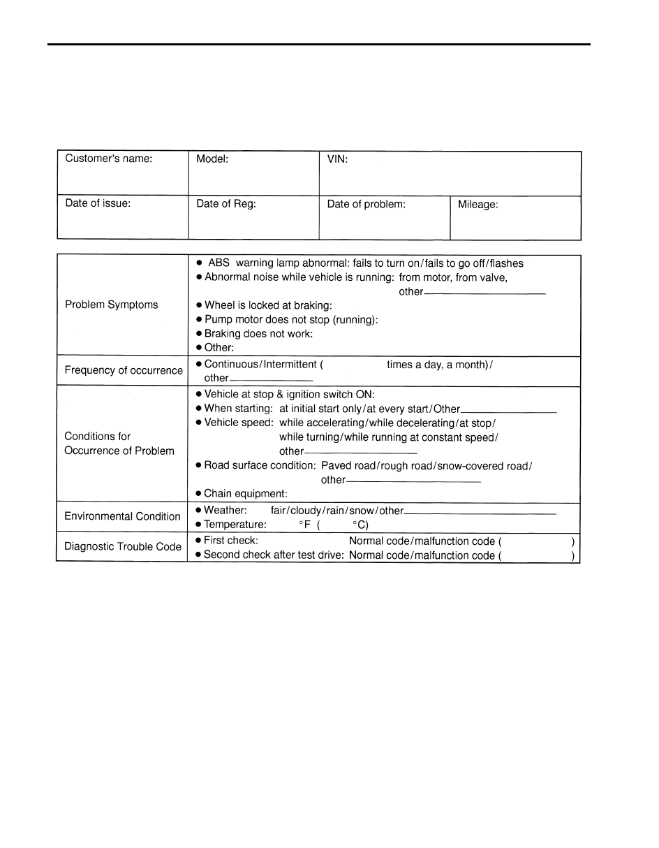
Customer complaint analysis
Record details of the problem (failure, complaint) and how it occurred as described by the customer.
For this purpose, use of such a questionnaire form as shown in the following will facilitate collecting information to the
point required for proper analysis and diagnosis.
Customer questionnaire (Example)
Problem symptom confirmation
Check if what the customer claimed in “Customer Questionnaire” is actually found in the vehicle and if that symptom is
found, whether it is identified as a failure. (This step should be shared with the customer if possible.) Check warning
lights related to brake system referring to “EBD Warning Light (Brake Warning Light) Check” and “ABS Warning Light
Check”.
DTC check, record and clearance
Perform “DTC Check” procedure, record it and then clear it referring to “DTC Clearance”.
Recheck DTC referring to “DTC Check”.
When DTC which is recorded at DTC check procedure is detected again after performing DTC clearance, go to “Step
4: ABS Check: ” to proceed the diagnosis.
When DTC which is recorded at DTC check procedure is not indicated anymore after performing DTC clearance, ABS
(ESP
®) control module does not perform the system diagnosis, or temporary abnormality may occur, therefore go to
“Step 2: Driving Test: ” to proceed the diagnosis.
I2RH01450014-01
ABS: 4E-10
Step 2: Driving Test
Test drive the vehicle at 40 km/h for more than a minute and check if any trouble symptom (such as abnormal lighting
of ABS warning light) exists.
If the malfunction DTC is confirmed again at ignition switch ON, driving test as described is not necessary. Proceed to
Step 3.
Step 3: DTC Check
Recheck DTC referring to “DTC Check”.
Step 4: ABS Check
According to ABS Check for the DTC confirmation in Step 3, locate the cause of the trouble, namely in a sensor,
switch, wire harness, connector, actuator assembly or other part and repair or replace faulty parts.
Step 5: Brakes Diagnosis
Check the parts or system suspected as a possible cause referring to “Brakes Symptom Diagnosis in Section 4A” and
based on symptoms appearing on the vehicle (symptom obtained through Steps 1 and 2 and repair or replace faulty
parts, if any).
Step 6: Check for Intermittent Problem
Check parts where an intermittent trouble is easy to occur (e.g., wire harness, connector, etc.), referring to
“Intermittent and Poor Connection Inspection in Section 00” and related circuit of trouble code recorded in Step 1 to 3.
Step 7: Final Confirmation Test
Confirm that the problem symptom has gone and the ABS is free from any abnormal conditions. If what has been
repaired is related to the malfunction DTC, clear the DTC once referring to “DTC Clearance” and perform test driving
and confirm that no DTC is indicated.
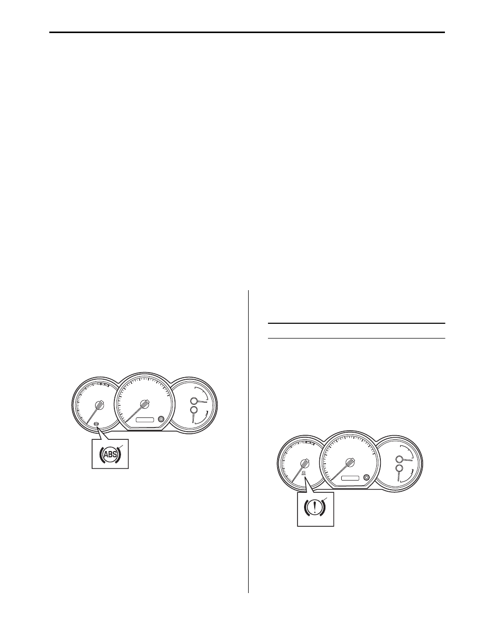
ABS Warning Light Check
S6JB0B4504002
1) Turn ignition switch ON.
2) Check that ABS warning light (1) comes ON for
about 2 seconds and then goes off.
If any faulty condition is found, advance to “ABS
Warning Light Does Not Come ON at Ignition Switch
ON” or “ABS Warning Light Comes ON Steady”.
EBD Warning Light (Brake Warning Light)
Check
S6JB0B4504003
NOTE
Perform this check on a level place.
1) Turn ignition switch ON with parking brake applied.
2) Check that EBD warning light (brake warning light)
(1) is turned ON.
3) Release parking brake with ignition switch ON and
check that EBD warning light (brake warning light)
goes off.
If it doesn’t go off, go to “EBD Warning Light (Brake
Warning Light) Comes ON Steady”.
1
I5JB0A450001-01
BRAKE
1
I5JB0A450007-01
4E-11 ABS:
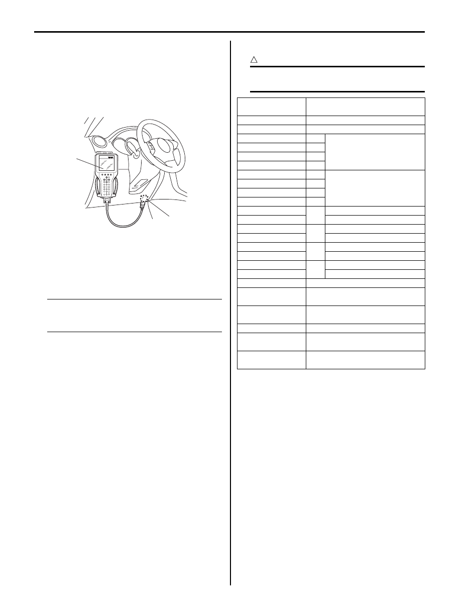
DTC Check
S6JB0B4504004
1) Turn ignition switch to OFF position.
2) Connect SUZUKI scan tool to data link connector
(1).
Special tool
(A): SUZUKI scan tool
3) Turn ignition switch to ON position.
4) Read DTC according to instructions displayed on
SUZUKI scan tool and print it or write it down. Refer
to SUZUKI scan tool operator’s manual for further
details.
NOTE
If SUZUKI scan tool can not communicate
ABS (ESP
®) hydraulic unit / control module,
perform “Serial Data Link Circuit Check”.
5) After completing the check, turn ignition switch off
and disconnect SUZUKI scan tool from DLC.
DTC Table
S6JB0B4504005
CAUTION
!
Be sure to perform “ABS Check” before
starting diagnosis.
(A)
1
I5JB0A450008-01
DTC (displayed on
SUZUKI scan tool)
Diagnostic Items
NO DTC
Normal
C1015
G sensor circuit
C1021
RF
Wheel speed sensor circuit
C1025
LF
C1031
RR
C1035
LR
C1022
RF
Wheel speed sensor or
encoder
C1026
LF
C1032
RR
C1036
LR
C1041
RF
Inlet solenoid valve circuit
C1042
Outlet solenoid valve circuit
C1045
LF
Inlet solenoid valve circuit
C1046
Outlet solenoid valve circuit
C1051
RR
Inlet solenoid valve circuit
C1052
Outlet solenoid valve circuit
C1055
LR
Inlet solenoid valve circuit
C1056
Outlet solenoid valve circuit
C1057
Power source
C1061
ABS pump motor and/or motor
driver circuit
C1063
Solenoid valve power supply driver
circuit
ABS (ESP
®) control module
U1073
Control Module Communication
Bus Off
U1100
Lost Communication with ECM
(Reception error)
ABS: 4E-12
DTC Clearance
S6JB0B4504006
WARNING
!
When performing a driving test, select a safe
place where there is neither any traffic nor
any traffic accident possibility and be very
careful during testing to avoid occurrence of
an accident.
After repair or replace malfunction part(s), clear all DTCs
by performing the following procedure or using SUZUKI
scan tool.
1) Connect SUZUKI scan tool to data link connector in
the same manner as when making this connection
for DTC check.
2) Turn ignition switch to ON position.
3) Erase DTC according to instructions displayed on
scan tool. Refer to scan tool operator’s manual for
further derails.
NOTE
For DTC C 1021, C1022, C1025, C1026, C1031,
C1032, C1035, C1036 and C1061, confirm that
ABS warning light turns off after performing
Step 2 of “Test Driving” under “ABS Check”,
and then clear the DTCs.
4) After completing the clearance, turn ignition switch
OFF and disconnect scan tool from data link
connector.
5) Perform “Driving Test” (Step 2 of “ABS Check”) and
“DTC Check” and confirm that NO DTC is displayed
on scan tool.
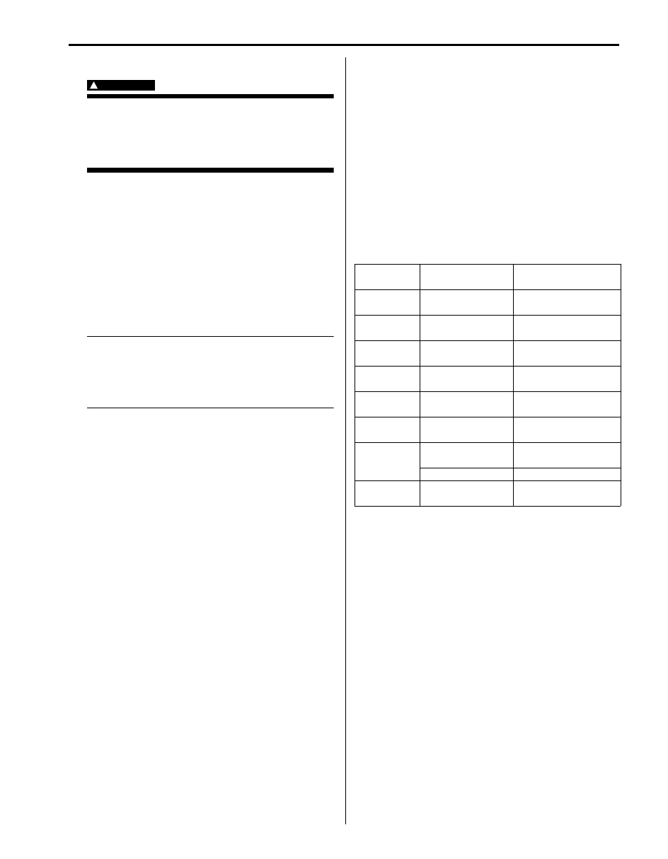
Scan Tool Data
S6JB0B4504007
The parameter data below are values measured with the
scan tool when the normally operating vehicle is under
the following conditions. When taking measurements for
comparison by using the scan tool, be sure to check that
the vehicle is under the following conditions.
• Apply parking brake and block wheels.
• Ignition switch ON.
• Turn OFF air conditioner (if equipped).
• Apply no load to power steering (if equipped). (Don’t
turn it)
• Turn OFF all electric loads (except ignition).
• No DTC.
• ABS is not operated. (Normal braking operation)
Scan Tool Data Definition
Battery Volt (V): Battery Voltage is an analog input
signal read by the ABS (ESP
®) control module.
Certain ABS (ESP
®) control module functions will be
modified if the battery voltage falls below or rises
above programmed thresholds.
Pump Motor Driver (V): This parameter indicates the
operational condition of the pump motor driver
(transistor).
RF Wheel Speed, LF Wheel Speed, RR Wheel Speed
and LF Wheel Speed (km/h, MPH): Wheel speed
is an ABS (ESP
®) control module internal
parameter. It is computed by reference pulses from
the wheel speed sensor.
Brake Switch (ON, OFF): This switch signal informs
the ABS (ESP
®) control module whether the brake
is active or not.
G Sensor (G): The G-Sensor converts gravity during
the vehicle acceleration / deceleration in to a voltage
conditions and controls the ABS for 4WD vehicle.
Scan Tool
Data
Standards
Condition
Battery
Voltage
10.0 – 16.0 V
—
Pump Motor
Driver
0.0 V
—
RF Wheel
Speed
0 km/h, 0.0 MPH Vehicle stop
LF Wheel
Speed
0 km/h, 0.0 MPH Vehicle stop
RR Wheel
Speed
0 km/h, 0.0 MPH Vehicle stop
LR Wheel
Speed
0 km/h, 0.0 MPH Vehicle stop
Brake Switch
ON
Brake pedal
depressed
OFF
Brake pedal released
G sensor
0
± 0.09G
Place vehicle on the
level
Нет комментариевНе стесняйтесь поделиться с нами вашим ценным мнением.
Текст