Suzuki Grand Vitara JB627. Manual — part 181

4E-5 ABS:
ABS Wiring Circuit Diagram
S6JB0B4502002
5. Solenoid valve driver (transistor)
13. Data link connector
21. ECM
6. Pump motor driver (transistor)
14. Wheel speed sensor (Right-front)
22. 4 way joint
7. Solenoid valve
15. Wheel speed sensor (Left-front)
8. Pump motor
16. Wheel speed sensor (Right-rear)
WHT/RED
WHT/GRN
BLK/YEL
WHT/RED
M
12V
GRN/ORN
1
2
3
4
8
10
11
12
13
[A]
14
15
16
17
18
19
20
21
22
23
24
25
1
2
3
4
5
6
7
8
9
10
11
12
13
26
E03
12V
5V
12V
23
24
VCC
22
a
WHT/BLU
WHT/BLU
14
15
16
17
PPL/WHT
18
19
+BB
PPL/RED
WHT
GRN
GRN/WHT
BLK
WHT
BLK
WHT
BLU/BLK
GRN/BLK
BLU
GRN
YEL/BLK
YEL
LT GRN
LT GRN/BLK
E03-21
E03-22
E03-19
E03-18
E03-15
E03-16
E03-25
E03-24
E03-7
E03-13
E03-26
BLK
BLK
E03-5
E03-14
E03-1
RED/BLK
RED/BLK
E03-12
E03-6
RED
WHT
RED
WHT
WHT/RED
WHT/BLU
E03-10
E03-8
RED
WHT
12V
12V
12V
12V
12V
BLK
WHT
BLK
WHT
20
26
29
28
27
21
7
6
5
32
32
30
31
25
9
32
I5JB0A450005-02
[A]: Terminal arrangement of ABS (ESP
®) hydraulic unit /
control module assembly
11. ABS pump motor driver (transistor)
23. Internal memory
a: Upside
12. Pump motor
24. Solenoid valve driver (transistor)
1. Battery
13. Solenoid valves
25. G sensor (4WD model)
2. Main fuse box
14. Right-rear wheel speed sensor
26. ECM
3. Ignition switch
15. Left-rear wheel speed sensor
27. BCM

ABS: 4E-6
4. Circuit fuse box
16. Right-front wheel speed sensor
28. Brake fluid level switch
5. Combination meter
17. Left-front wheel speed sensor
29. Parking brake switch
6. ABS warning light
18. Data link connector
30. CAN junction
7. EBD warning light (Brake warning light)
19. To ECM, TCM, SDM, BCM and 4WD
control module
31. To TCM, 4WD control module and keyless
start control module
8. Light driver module
20. Stop light
32. CAN communication line
9. ABS (ESP
®) hydraulic unit / control module
assembly
21. Brake light switch
10. Solenoid valve power supply driver (transistor)
22. Power control unit
Terminal
Wire color
Circuit
E03
1
WHT/BLU
ABS pump motor driver (Transistor)
2
—
—
3
—
—
4
—
—
5
PPL/WHT
DATA link connector
6
WHT
CAN communication line (low) for combination meter
7
GRN/ORN
Ignition switch
8
WHT/BLU
CAN communication line (low) for ECM
9
—
—
10
WHT/RED
CAN communication line (high) for ECM
11
—
—
12
RED
CAN communication line (high) for combination meter
13
BLK
Ground
14
WHT/RED
Solenoid valve power supply driver (Transistor)
15
YEL/BLK
Left–rear wheel speed sensor (–)
16
YEL
Left–rear wheel speed sensor (+)
17
—
—
18
GRN
Right–front wheel speed sensor (+)
19
GRN/BLK
Right–front wheel speed sensor (–)
20
—
—
21
BLU/BLK
Left–front wheel speed sensor (–)
22
BLU
Left–front wheel speed sensor (+)
23
—
—
24
LT GRN
Right–rear wheel speed sensor (+)
25
LT GRN/BLK
Right–rear wheel speed sensor (–)
26
BLK
Ground
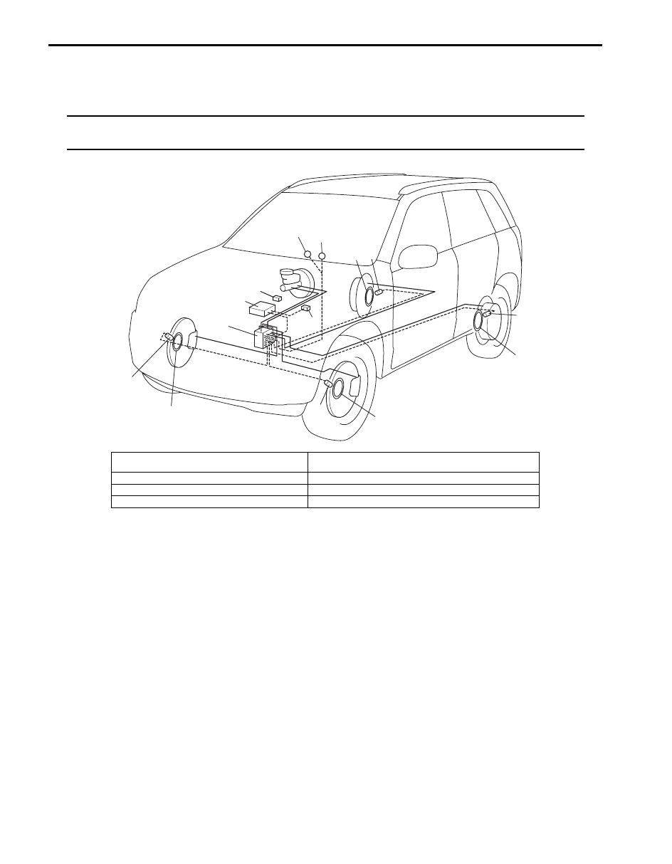
4E-7 ABS:
Component Location
ABS Components Location
S6JB0B4503001
NOTE
As for the difference of RHD model and LHD model, the location of the combination meter, data link
connector, brake light switch and the brake master cylinder assembly only changes.
6
2
1
7
4
5
6
2
3
2
6
6
2
8
I5JB0A450006-01
1. ABS (ESP
®) hydraulic unit / control module
assembly
5. EBD warning light (Brake warning light)
2. Wheel speed sensors
6. Wheel encoder (included in wheel hub assembly)
3. Brake light switch
7. Data link connector
4. ABS warning light
8. ECM

ABS: 4E-8
Diagnostic Information and Procedures
ABS Check
S6JB0B4504001
Refer to the following items for the details of each step.
Step
Action
Yes
No
1
Malfunction analysis
1) Perform “Customer complaint analysis: ”.
2) Perform “Problem symptom confirmation: ”.
3) Perform “DTC check, record and clearance: ” and
recheck DTC.
Is there any malfunction DTC?
Go to Step 4.
Go to Step 2.
2
Driving test
1) Perform “Step 2: Driving Test: ”.
Is trouble symptom identified?
Go to Step 3.
Go to Step 6.
3
DTC check
1) Perform “DTC Check”.
Is it malfunction code?
Go to Step 4.
Go to Step 5.
4
ABS check
1) Inspect and repair referring to applicable DTC flow.
Does trouble recur?
Go to Step 5.
Go to Step 7.
5
Brakes diagnosis
1) Inspect and repair referring to “Brakes Symptom
Does trouble recur?
Go to Step 3.
Go to Step 7.
6
Check for intermittent problem
1) Check intermittent troubles referring to “Intermittent and
Poor Connection Inspection in Section 00” and related
circuit of trouble code recorded in Step 1.
Does trouble recur?
Go to Step 4.
Go to Step 7.
7
Final confirmation test
1) Perform “Step 7: Final Confirmation Test: ”.
Does trouble recur?
Go to Step 3.
End.
Нет комментариевНе стесняйтесь поделиться с нами вашим ценным мнением.
Текст