Suzuki Grand Vitara JB627. Manual — part 178
4C-3 Rear Brakes:
Cracked, scored, or grooved drum
A cracked, drum is unsafe for further service and must
be replaced.
Do not attempt to weld a cracked drum.
Smooth up any slight scores. Heavy or extensive scoring
will cause excessive brake lining wear and it will
probably be necessary to resurface drum braking
surface.
If brake linings are slightly worn and drum is grooved,
drum should be polished with fine emery cloth but should
no be turned.
NOTE
When drum is removed, visually inspect
wheel cylinder for brake fluid leakage.
Correct leaky point, if any.
Brake Shoe
CAUTION
!
Never polish lining with sandpaper. If lining is
polished with sandpaper, hard particles of
sandpaper will be deposited in lining and
may damage drum. When it is required to
correct lining, replace it with a new one.
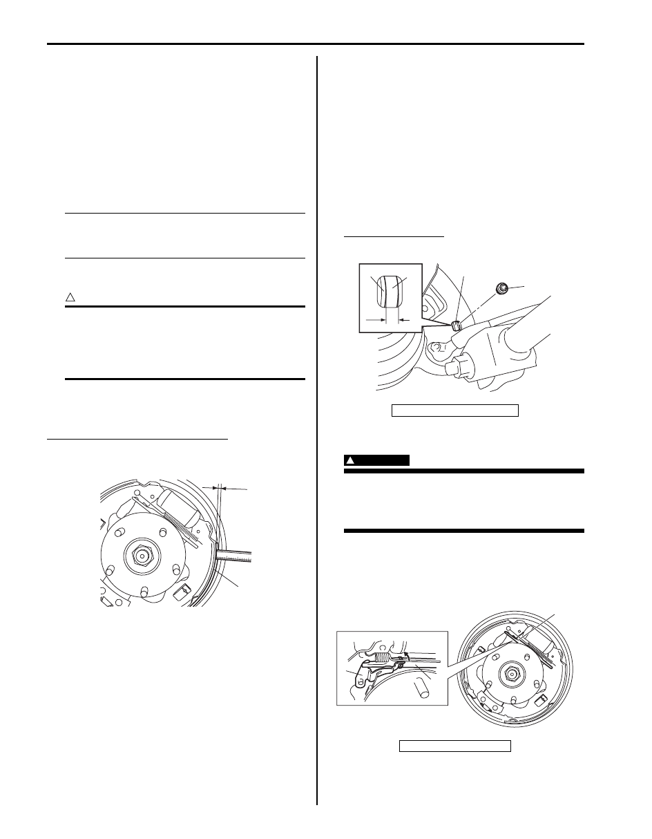
Measure the minimum thickness of brake lining (1). Also,
check surface of lining for hardening, excessive wear
and oil.
Rear brake shoe lining thickness “a”
Standard: 4.5 mm (0.18 in.)
Limit: 1.0 mm (0.04 in.)
Rear Brake Shoe On-Vehicle Check
S6JB0B4306004
Inspection should be carried out on the following points
after brake pedal travel (pedal to silencer clearance)
check as described on “Excessive Pedal Travel Check in
Section 4A”, even when it is more than specification.
Amount of brake shoe wear can be checked as follows.
1) Hoist vehicle.
2) Remove rubber plug (1) from brake back plate.
3) Through hole of back plate, visually check for
thickness of brake shoe lining (2). If lining thickness
less than specified wear limit, replace with new
brake shoes.
Lining thickness “a”
Service limit: 1.0 mm (0.04 in.)
Rear Brake Shoe Removal and Installation
S6JB0B4306005
WARNING
!
Use special care when installing brake shoe
return spring. Failure in its proper installation
may allow it to springback and cause
personal injury.
Removal
1) Remove brake drum referring to “Rear Brake Drum
2) Fully turn adjuster (1) to reduce brake shoe adjuster.
“a”
1
I5JB0A430004-02
3. Brake shoe rim
2. Adjuster pawl lever
2
3
“a”
2
1
I5JB0A430005-01
1
2
1
I5JB0A430019-01
Rear Brakes: 4C-4
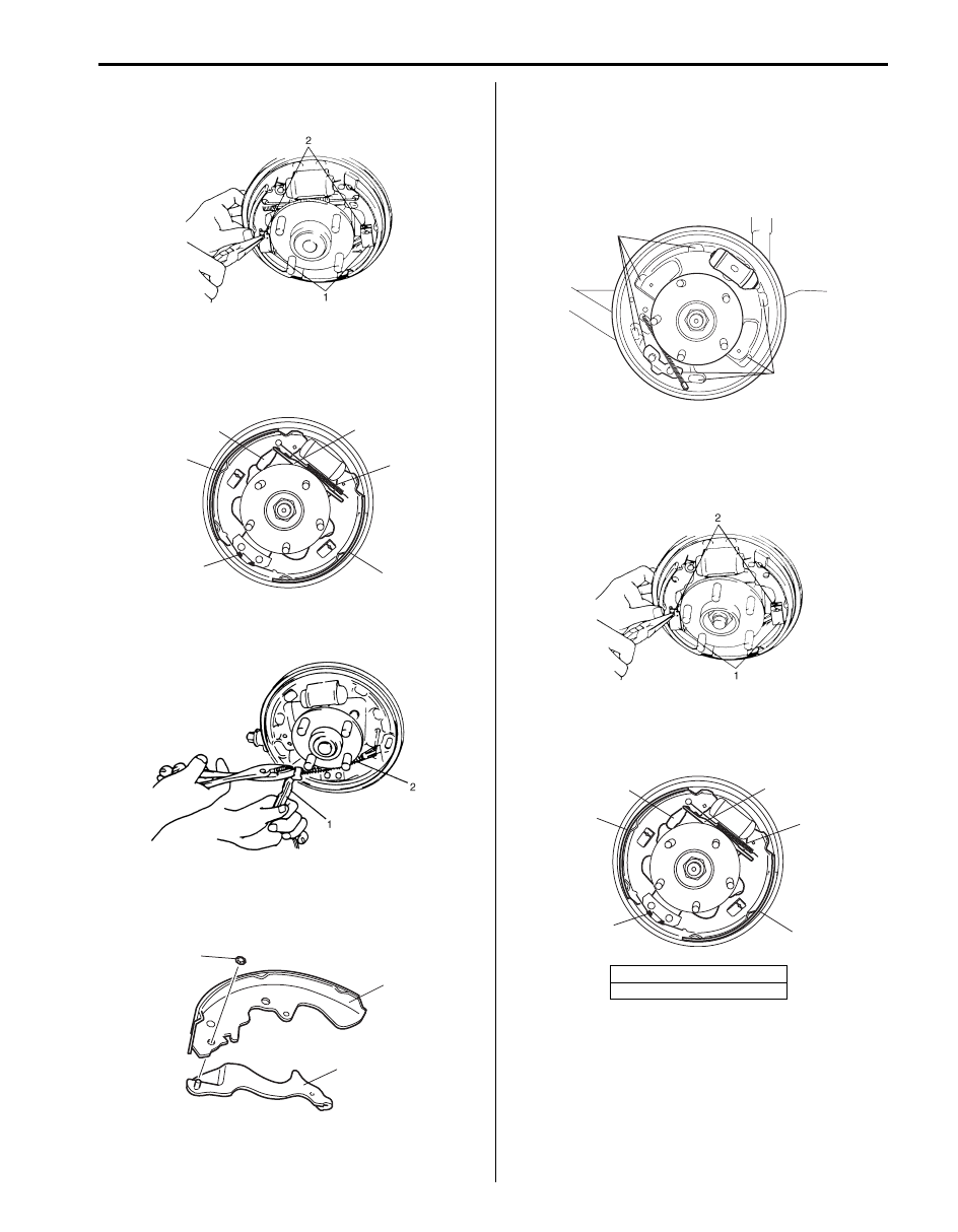
3) Remove shoe hold down springs (1) by turning shoe
hold down pins (2).
4) Remove upper shoe return spring (1), brake adjuster
(2), adjuster pawl lever (3) and spring.
5) Remove brake shoes (4) and lower shoe return
spring (5).
6) Disconnect parking brake shoe lever (1) from
parking brake cable (2).
7) Remove push nut (1).
8) Remove parking brake shoe lever (2) from brake
shoe (3).
Installation
1) Assemble parts in reverse order of removal
procedure.
2) Before installing rear brake shoe to brake back plate,
clean brake back plate and apply high-temperature
grease to “a” on which shoe rims rest.
3) Before install brake shoe, be sure to fully turn brake
adjuster to reduce.
4) Install shoe hold down springs (1) by pushing them
down in place and turning hold down pins (2).
5) Install brake adjuster (2) and upper shoe return
spring (1).
6) Install adjuster pawl lever (3) and adjuster spring.
7) For procedure hereafter, refer to “Rear Brake Drum
I2RH01430012-01
3
2
4
1
4
5
I5JB0A430006-01
I2RH01430013-01
2
3
1
I5JB0A430007-01
4. Brake shoe
5. Lower shoe return spring
“a”
“a”
I6JB0B430002-02
I5JB0A430010-01
3
2
4
1
4
5
I5JB0A430006-01
4C-5 Rear Brakes:
Rear Brake Shoe Inspection
S6JB0B4306006
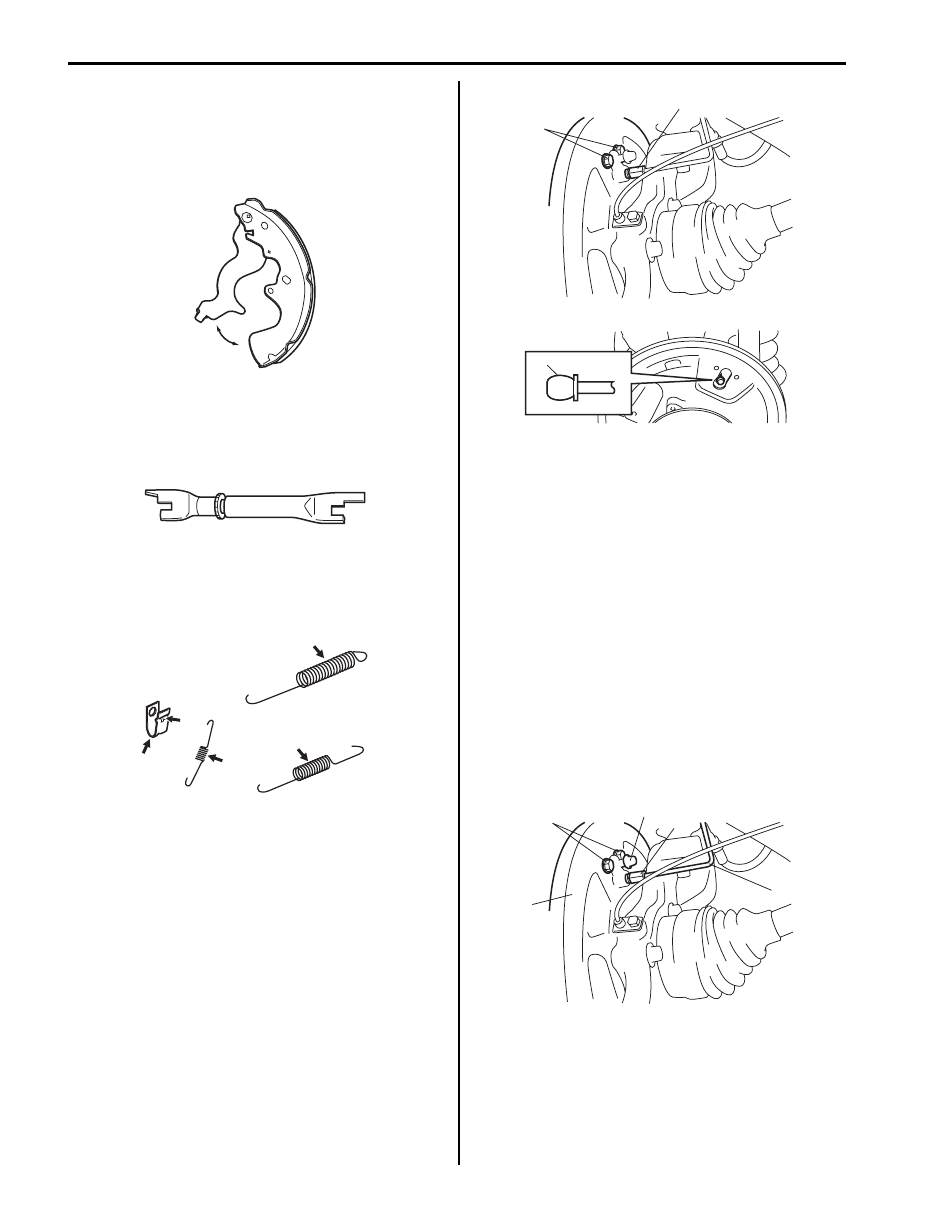
Parking Brake Shoe Lever
Inspect brake shoe lever for free movement against
brake shoe web. If defective, correct or replace.
Brake Adjuster
Check thread or ratchet of adjuster for wear, sticking and
corrosion.
If found defective, replace brake adjuster.
Springs
Inspect for damage or weakening.
Inspect each part with arrow for rust. If found defective,
replace.
Brake Shoe
Refer to “Rear Brake Drum and Shoe Inspection”.
Wheel Cylinder Removal and Installation
S6JB0B4306007
Removal
1) Remove brake drum referring to “Rear Brake Drum
2) Remove brake shoe referring to “Rear Brake Shoe
3) Loosen brake pipe flare nut (1) but only within the
extent that fluid does not leak.
4) Remove wheel cylinder mounting bolts (2).
Disconnect brake pipe from wheel cylinder and put
wheel cylinder bleeder plug cap (3) onto pipe to
prevent fluid from spilling.
Installation
1) Fit wheel cylinder to brake back plate, take off
bleeder plug cap from brake pipe and connect pipe
to wheel cylinder just enough to prevent fluid from
leaking.
2) Tighten wheel cylinder mounting bolts to brake back
plate (1) to specified torque.
Tightening torque
Wheel cylinder mounting bolt (a): 13 N·m (1.3
kgf-m, 9.5 lb-ft)
3) Tighten flare nut of brake pipe (2) to specified torque.
Tightening torque
Brake pipe flare nut (b): 16 N·m (1.6 kgf-m, 12.0
lb-ft)
4) Install bleeder plug cap (3) taken off from pipe back
to bleeder plug.
I5JB0A430009-02
I5JB0A430011-01
I5JB0A430012-02
3
2
1
I5JB0A430013-01
2
(b)
3
(a)
1
I5JB0A430014-01
Rear Brakes: 4C-6
5) Install brake shoe referring to “Rear Brake Shoe
6) Install brake drum referring to step 1) to 2) of
“Installation” in “Rear Brake Drum Removal and
Installation”.
7) Fill reservoir with brake fluid and bleed brake
system. For bleeding operation refer to “Air Bleeding
of Brake System in Section 4A”.
8) Adjust, check brake and install rear wheel referring
to step 3) to 5) of “Installation” in “Rear Brake Drum
Removal and Installation”.
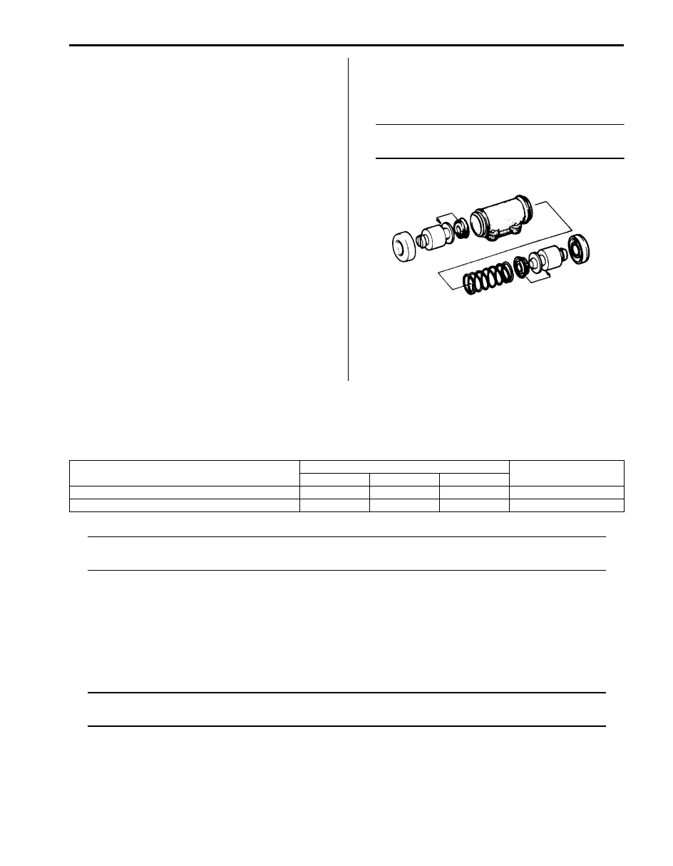
Wheel Cylinder Inspection
S6JB0B4306008
Inspect wheel cylinder disassembled parts for wear,
cracks, corrosion or damage.
NOTE
Clean wheel cylinder components with brake
fluid.
Rear Brake Back Plate Removal and Installation
S6JB0B4306009
Refer to “Rear Wheel Hub Assembly Removal and
Installation in Section 2C”.
Specifications
Tightening Torque Specifications
S6JB0B4307001
NOTE
The specified tightening torque is also described in the following.
“Rear Drum Brake Assembly Components”
Reference:
For the tightening torque of fastener not specified in this section, refer to “Fastener Information in Section 0A”.
Special Tools and Equipment
Recommended Service Material
S6JB0B4308001
NOTE
Required service material is also described in the following.
“Rear Drum Brake Assembly Components”
IYSQ01430019-01
Fastening part
Tightening torque
Note
N
⋅m
kgf-m
lb-ft
Wheel cylinder mounting bolt
13
1.3
9.5
Brake pipe flare nut
16
1.6
12.0
Нет комментариевНе стесняйтесь поделиться с нами вашим ценным мнением.
Текст