Suzuki Grand Vitara JB627. Manual — part 231

5A-108 Automatic Transmission/Transaxle:
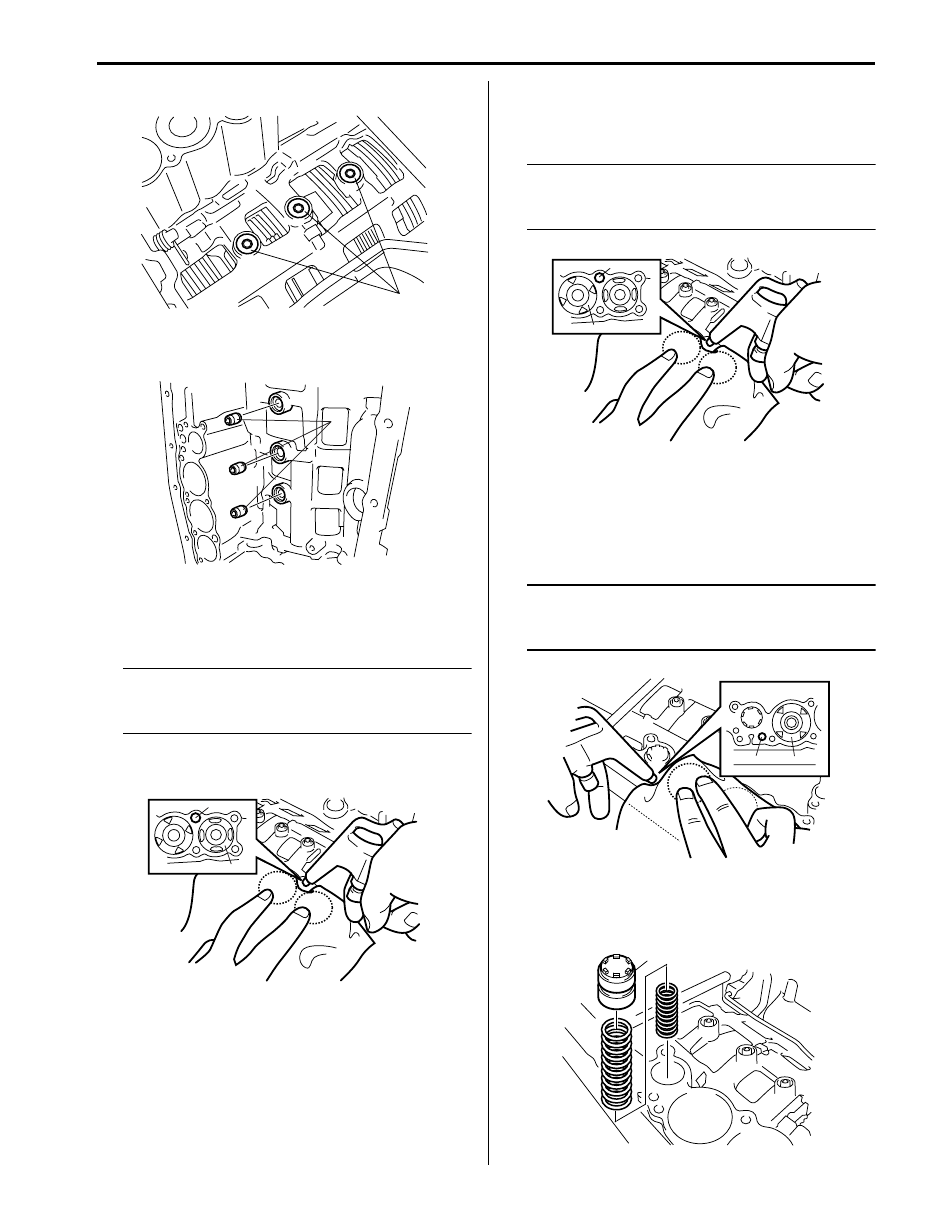
10) Remove oil pan bolts (1).
11) Remove oil pan and oil pan gasket from
transmission case.
12) Remove the 4 magnets (1) and clean them to steel
particles etc.
13) Remove oil strainer (1) from valve body assembly.
14) Remove transmission fluid temperature sensor A (1)
and B (4) (if equipped) from sensor clamps (2).
15) Remove wire harness clamp (3).
16) Disconnect the following connectors from shift
solenoid-A, shift solenoid-B, shift solenoid-E, TCC
solenoid, pressure control solenoid-A, pressure
control solenoid-B and pressure control solenoid-C.
17) After removing bolt (1) pull out transmission wire
connector (2) from transmission case.
CAUTION
!
When pulling transmission wire harness out
of transmission case, take care not to
damage connectors and transmission fluid
temperature sensors at narrow exist of case.
18) Remove spring plate (1) and manual shift lever
spring (2).
19) Remove valve body assembly (3) by removing 19
bolts.
20) Remove check ball body (1) and spring (2).
1
I4JA01512066-01
1
I4JA01512067-01
1
I4JA01512068-01
2
1
4
2
3
I6JB0B510009-01
2
1
I4JA01512070-01
3
1
2
I4JA01512071-01
1
2
I4JA01512072-01
Automatic Transmission/Transaxle: 5A-109
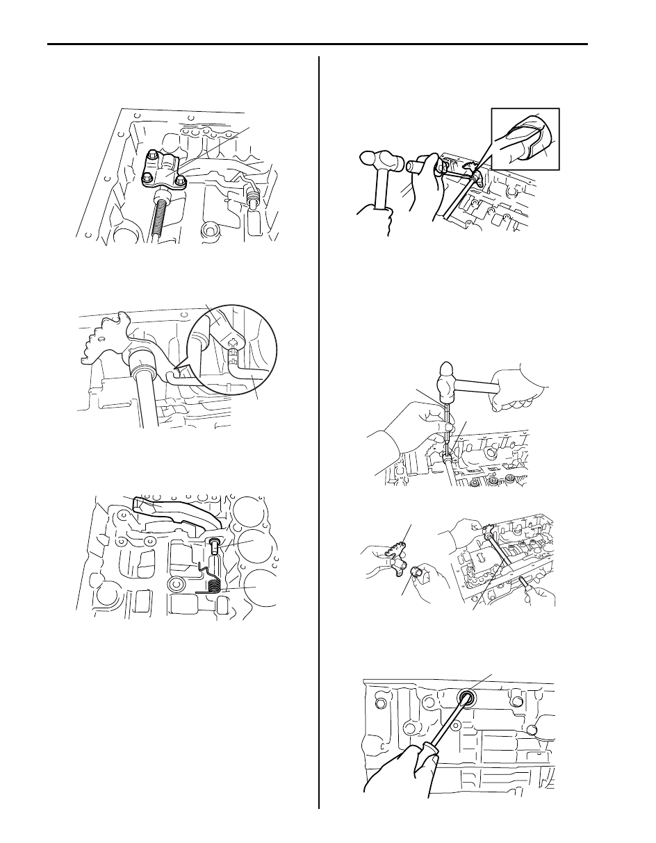
21) Remove transmission case gaskets (1).
22) Remove brake drum gaskets (1) from transmission
case.
23) Remove direct clutch accumulator piston (1) by
compressed air (392 kPa, 4.0 kg/cm
2
, 57 psi) into
hole (2).
NOTE
Cover accumulator piston (1) with shop cloth
while blowing because A/T fluid should be
spattered.
24) Remove direct clutch accumulator piston spring from
transmission case.
25) Remove 2nd (No.3) brake accumulator piston (1) by
compressed air (392 kPa, 4.0 kg/cm
2
, 57 psi) into
hole (2).
NOTE
Cover accumulator piston (1) with shop cloth
while blowing because A/T fluid should be
spattered.
26) Remove 2nd (No.3) brake accumulator piston spring
from transmission case.
27) Remove reverse clutch accumulator piston (1) by
compressed air (392 kPa, 4.0 kg/cm
2
, 57 psi) into
hole (2).
NOTE
Cover accumulator piston (1) with shop cloth
while blowing because A/T fluid should be
spattered.
28) Remove reverse clutch accumulator piston springs
from transmission case.
29) Remove forward clutch accumulator piston (1).
1
I4JA01512073-01
1
I4JA01512074-01
2
1
I4JA01512075-01
1
2
I4JA01512076-01
1
2
I4JA01512077-01
1
I4JA01512078-01
5A-110 Automatic Transmission/Transaxle:
30) Remove forward clutch accumulator piston springs
from transmission case.
31) Remove parking pawl bracket (1).
32) Remove parking lock rod (2) from manual shift lever
(1).
33) Pull out parking pawl pin (1) to oil pump side and
then remove parking lock pawl (2) and parking pawl
spring (3).
34) Remove manual shift shaft and lever as follows.
a) Undo caulking of sleeve cover (1) by using flat
end rod or the like and hammer.
b) Drive out manual shift lever pin (1) by using
special tool and hammer.
Special tool
(A): 09922–89810
c) Pull out manual shift shaft (2) from transmission
case, and then remove manual shift lever (3) and
sleeve cover (4).
35) Remove 2 manual shift shaft oil seals (1) from
transmission case by using flat end rod or the like.
1
I4JA01512079-01
2
1
I4JA01512080-01
2
1
3
I4JA01512081-01
1
I4JA01512082-01
1
3
(A)
2
4
I4JA01512083-01
1
I4JA01512084-01
Automatic Transmission/Transaxle: 5A-111
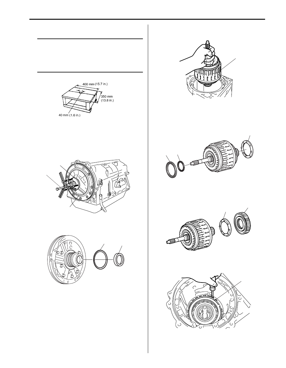
36) Place transmission on stand facing oil pump upward.
NOTE
• To prevent transmission case from getting
damaged, protect its contacting surface
with stand by using shop cloth or the like.
• A stand of such size as shown in the figure
will facilitate work.
37) After removing oil pump bolts, remove oil pump
assembly (1) by using special tool.
Special tool
(A): 09927–66520
(B): 09920–13120
38) Remove thrust bearing race No.1 (1) and thrust
bearing race No.10 (2) from oil pump assembly.
39) Remove clutch drum and input shaft assembly (1)
from transmission case.
40) Remove clutch hub thrust washer (1) and thrust
needle roller bearing No.1 (2) and thrust needle
roller bearing (3) from clutch drum and input shaft
assembly.
41) Remove one-way No.2 clutch assembly (1) and
clutch drum thrust washer No.2 (2) from clutch drum
& input shaft assembly.
42) Remove snap ring (1) by using flat end rod or the
like.
I4JA01512086-01
(A)
(B)
1
I4JA01512351-01
2
1
I6JB01510034-01
1
I4JA01512088-01
2
3
1
I6JB01510035-01
1
2
I4JA01512090-01
1
I4JA01512091-01
Нет комментариевНе стесняйтесь поделиться с нами вашим ценным мнением.
Текст