Suzuki Grand Vitara JB627. Manual — part 230
5A-104 Automatic Transmission/Transaxle:
Automatic Transmission Assembly
Dismounting and Remounting
S6JB0B5106029
Dismounting
1) Dismount engine with transmission and transfer
referring to “Engine Assembly Removal and
Installation in Section 1D”.
2) Remove transfer from transmission.
3) Remove engine rear mounting member and rear
mounting.
4) Remove exhaust manifold left and right bracket.
5) Remove cooler hose and cooler pipe No.1.
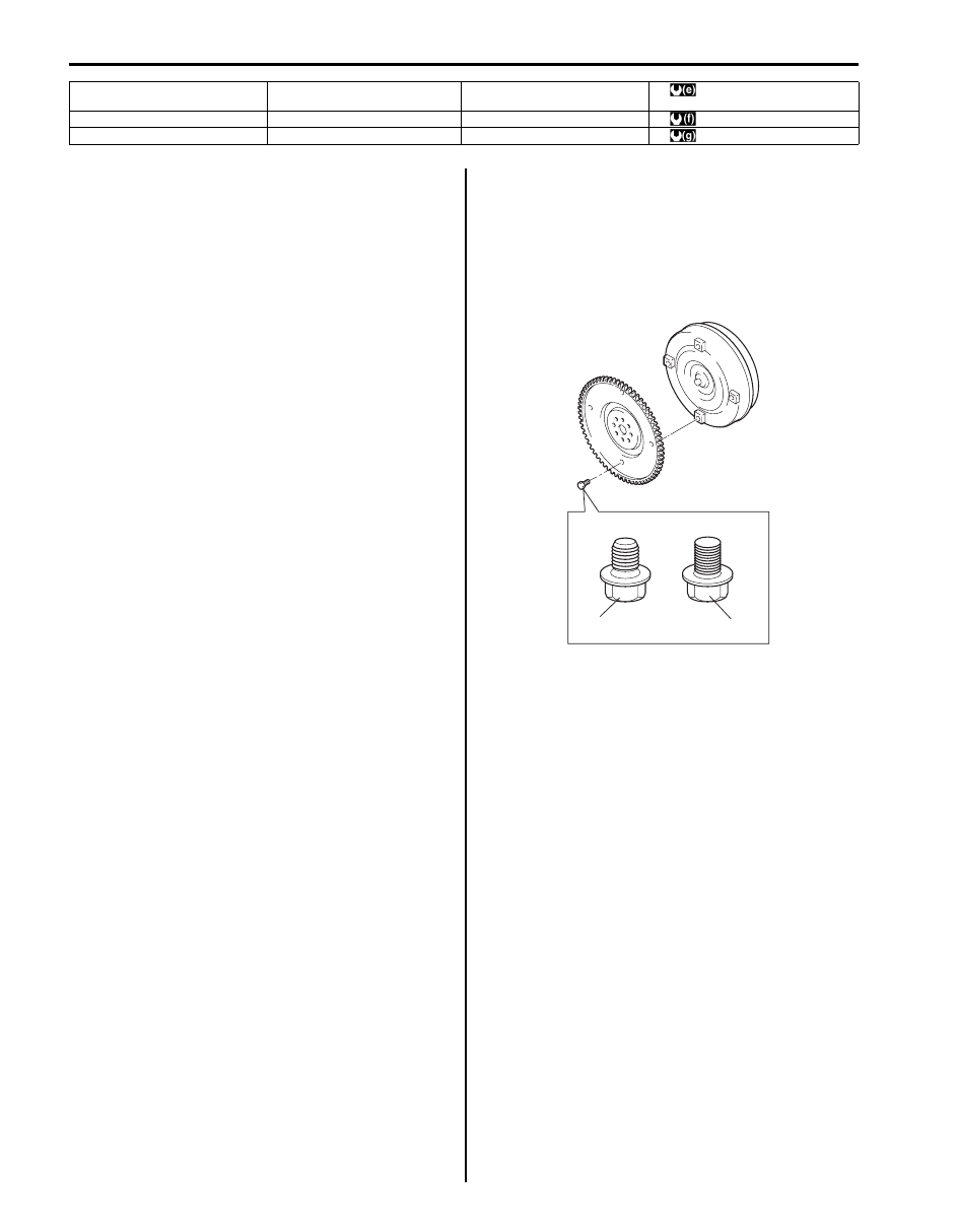
6) Remove drive plate cover, and then remove drive
plate bolts by holding crankshaft pulley bolt
stationary.
7) Remove Starting Motor referring to “Starting Motor
Dismounting and Remounting in Section 1I”.
8) Remove transmission assembly from engine
assembly.
Installation
For remounting, reverse dismounting procedure noting
the following points.
• Tighten each bolts and nuts referring to “Automatic
• Tighten drive plate bolt No.1 (1) first and then tighten
drive plate bolts No.2 (2).
• Set each clamp for wiring securely.
• Fill A/T fluid referring to “A/T Fluid Change”.
• Connect battery and check function of engine and
transmission.
8. Drive plate cover
18. Input shaft speed sensor
28. Engine rear mounting bracket
bolt
: 23 N
⋅m (2.3 kgf-m, 17.0 lb-ft)
9. Oil cooler pipe No.1
19. Output shaft speed sensor
29. Mounting member bolt
: 55 N
⋅m (5.5 kgf-m, 40.0 lb-ft)
10. Exhaust manifold left bracket
20. Transmission wire connector
30. Starting motor
: 69 N
⋅m (6.9 kgf-m, 50.0 lb-ft)
1
2
I6JB01510031-01
Automatic Transmission/Transaxle: 5A-105
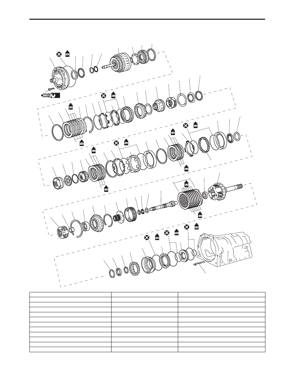
Automatic Transmission Unit Components
S6JB0B5106030
1
3
4
5
7
8
9
6
12
13
14
15
16
17
18
19
20
21
22
23
24
25
26
27
30
31
32
33 34
35
36
37
38
39
40
41
42
43
44
45
46
47
48
49
52
53
54
55
56
57
58
59
60
61
62
63
64
65
66
69
70
71
72
73
74
75
76
77
2
10
11
28
29
50
51
67
68
79
78
(a)
I6JB01510029-01
1. Oil pump assembly
29. Thrust needle roller bearing
57. Snap ring
2. Oil pump bolt
30. Front planetary ring gear
58. Rear planetary flange
3. O-ring
31. Front planetary ring gear flange
59. Rear planetary ring gear
4. Thrust bearing race No.1
32. Snap ring
60. Thrust bearing race No.7
5. Thrust needle roller bearing No.1
33. Middle planetary ring gear
61. Thrust needle roller bearing
6. Thrust bearing race No.10
34. No.1 brake flange
62. Thrust bearing race No.8
7. Thrust needle roller bearing
35. No.1 brake disc
63. Intermediate shaft
8. Clutch drum and input shaft assembly
36. No.1 brake plate
64. 1st & reverse (No.4) brake flange
9. Clutch drum thrust washer No.2
37. Snap ring
65. 1st & reverse (No.4) brake disc
10. One-way No.2 clutch assembly
38. No.1 brake piston return spring
66. 1st & reverse (No.4) brake plate
11. Clutch hub thrust washer
39. O-ring
67. Thrust needle roller bearing
12. Snap ring
40. No.1 brake piston
68. Rear planetary gear assembly
5A-106 Automatic Transmission/Transaxle:
Automatic Transmission Unit Disassembly
S6JB0B5106031
Reference: “Automatic Transmission Assembly
Dismounting and Remounting”
CAUTION
!
• Keep component parts in group for each
subassembly and avoid mixing them up.
• Clean all parts with cleaning solvent
thoroughly and air dry them.
• Use kerosene or automatic transmission
fluid as cleaning solvent.
• Do not use wiping cloths or rags to clean
or dry parts.
• All oil passages should be blown out and
checked to make sure that they are not
obstructed.
• Keep face and eyes away from solvent
spray while air blowing parts.
• Check mating surface for irregularities and
remove them, if any, and clean it again.
• Soak new clutch discs and brake discs in
transmission fluid for at least 2 hours
before assembly.
• Replace all gaskets and O-rings with new
ones.
• Apply automatic transmission fluid to all
O-rings.
• When installing seal ring, be careful so that
it is not expanded excessively, extruded or
caught.
• Replace oil seals that are removed and
apply grease to their lips.
• Before installing, be sure to apply
automatic transmission fluid to sliding,
rolling and thrusting surface of all
component parts. Also after installation,
make sure to check each part for proper
operation.
• Always use torque wrench when
tightening bolts.
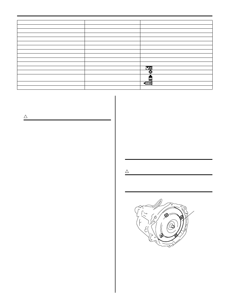
1) Extract torque converter (1) from transmission.
CAUTION
!
Remove torque converter as much straight
as possible.
Leaning it may cause to damage oil seal lip.
13. 2nd (No.3) brake flange
41. No.1 brake cylinder
69. Thrust bearing race No.9
14. 2nd (No.3) brake disc
42. Snap ring
70. Thrust needle roller bearing
15. 2nd (No.3) brake plate
43. No.2 brake flange
71. Snap ring
16. 2nd (No.3) brake cushion plate
44. No.2 brake disc
72. 1st & reverse (No.4) brake return spring
17. Snap ring
45. No.2 brake plate
73. 1st & reverse (No.4) brake piston
18. Snap ring
46. No.2 brake piston return spring
74. O-ring
19. 2nd (No.3) brake return spring
47. O-ring
75. Brake reaction sleeve
20. O-ring
48. No.2 brake piston
76. O-ring
21. 2nd (No.3) brake piston
49. No.2 brake cylinder
77. 1st & reverse (No.4) brake inner piston
22. 2nd (No.3) brake cylinder
50. Thrust needle roller bearing
78. O-ring
23. One-way No.1 clutch assembly
51. Thrust bearing race No.4
79. Brake plate stopper spring
24. Planetary carrier thrust washer No.1
52. Middle planetary gear assembly
: 21 N
⋅m (2.1 kgf-m, 15.5 lb-ft)
25. One-way No.1 clutch inner race
53. Planetary sun gear
: Do not reuse.
26. Front planetary gear assembly
54. Snap ring
: Apply A/T fluid
27. Planetary carrier thrust washer No.2
55. One-way No.3 clutch inner race
: Apply sealant 99000-31230 to bolt flange
28. Thrust bearing race No.3
56. One-way No.3 clutch assembly
1
I4JA01512052-01
Automatic Transmission/Transaxle: 5A-107
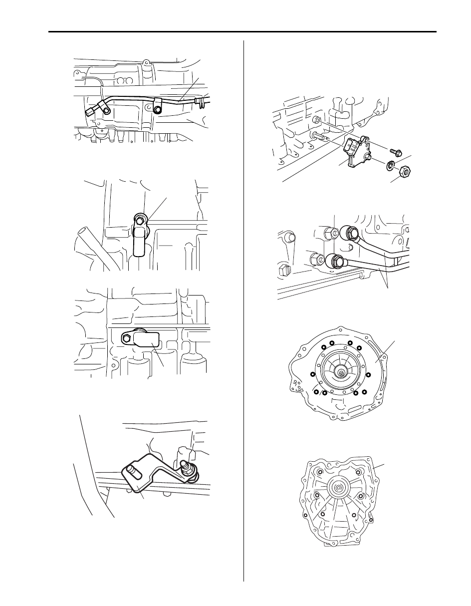
2) Remove breather pipe (1) from transmission.
3) Remove output shaft speed sensor (1) and input
shaft speed sensor (2).
4) Remove the nut, the washer and manual select lever
(1).
5) Unbend bend parts of lock washer (1) and then
remove manual shift shaft nut (2), lock washer and
grommet.
6) Remove transmission range sensor (3) by removing
sensor bolt.
7) Remove oil cooler pipes (1) from transmission.
8) Remove converter housing (1) by removing 10 bolts.
9) Remove transmission case adapter (1) by removing
8 bolts.
1
I4JA01512053-01
2
1
I5JA01512004-01
1
I6JB01510032-01
1
3
2
I4JA01512056-01
1
I6JB01510033-01
1
I4JA01512058-01
1
I4JA01512064-01
Нет комментариевНе стесняйтесь поделиться с нами вашим ценным мнением.
Текст