Suzuki Grand Vitara JB627. Manual — part 102
1F-2 Engine Cooling System:
Schematic and Routing Diagram
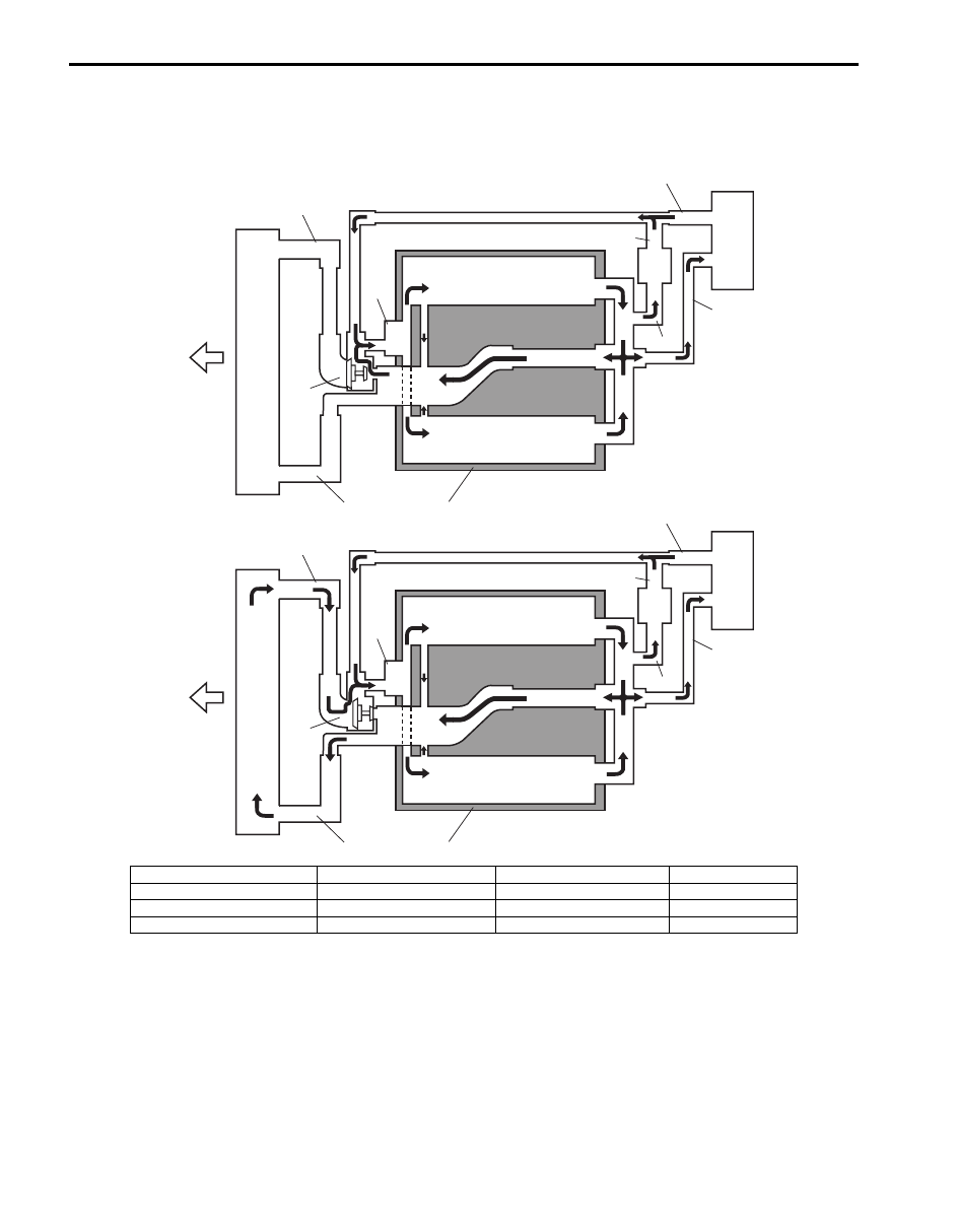
Coolant Circulation
S6JB0B1602001
1
2
3
4
5
6
7
8
9
10
11
12
13
[A]
1
2
3
4
5
6
7
8
9
10
11
12
13
[B]
I6JB01160015-01
[A]: When thermostat is close
3. Throttle body inlet hose
7. Throttle body
11. Heater core
[B]: When thermostat is open
4. Throttle body outlet hose
8. Engine
12. Radiator
1. Radiator inlet hose
5. Thermostat
9. Heater core inlet hose
13. Forward
2. Radiator outlet hose
6. Water pump
10. Heater core outlet hose
Engine Cooling System: 1F-3
Diagnostic Information and Procedures
Engine Cooling Symptom Diagnosis
S6JB0B1604001
Condition
Possible cause
Correction / Reference Item
Engine overheats
(Radiator fan operates)
Loose or broken water pump belt
Adjust or replace.
Not enough coolant
Check coolant level and add as necessary.
Faulty thermostat
Replace.
Faulty water pump
Replace.
Dirty or bent radiator fins
Clean or remedy.
Coolant leakage on cooling system
Repair.
Clogged radiator
Check and replace radiator as necessary.
Faulty radiator cap
Replace.
Improper ignition timing
Refer to “Ignition System Symptom Diagnosis
in Section 1H”.
Dragging brakes
Adjust brake.
Slipping clutch
Adjust or replace.
Poor charge battery
Check and replace as necessary.
Poor generation generator
Check and repair.
ECT sensor faulty
Check and replace as necessary.
Radiator cooling fan relay No.2 and/or
No.3 faulty
Check and replace as necessary.
Radiator fan motor faulty
Check and replace as necessary.
ECM faulty
Check and replace as necessary.
Wiring or grounding faulty
Repair as necessary.
Equipped with too much electric load
part(s)
Dismount.
Engine overheats
(Radiator fan does not
operate)
Fuse blown
Check radiator fan fuse of relay/fuse box and
check for short circuit to ground.
Radiator cooling fan relay No.1 faulty
Check and replace as necessary.
ECT sensor faulty
Check and replace as necessary.
Radiator cooling fan motor faulty
Check and replace as necessary.
Wiring or grounding faulty
Repair as necessary.
ECM faulty
Check and replace as necessary.
1F-4 Engine Cooling System:
Repair Instructions
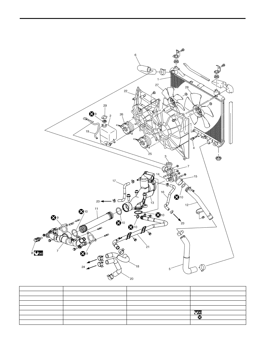
Cooling System Components
S6JB0B1606001
I6JB01160003-01
1. Radiator
9. Gasket
17. Left side cylinder head water hose
25. Main fan motor
2. Reservoir
10. O-ring
18. Heater outlet hose
26. Sub fan motor
3. Radiator cap
11. Water outlet pipe
19. Reservoir hose
27. Sub fan
4. Drain plug
12. Water inlet pipe
20. Heater inlet hose
28. Main fan
5. Radiator outlet hose
13. Thermostat case
21. Heater outlet pipe
29. Reservoir cap
6. Radiator inlet hose
14. Thermostat
22. Fan shroud
: 12 N
⋅m (1.2 kgf-m, 9.0 lb-ft)
7. Water outlet cap
15. Thermostat cap
23. To cylinder head
: Do not reuse.
8. ECT sensor
16. Right side cylinder head water hose
24. To heater core
Engine Cooling System: 1F-5
Coolant Level Check
S6JB0B1606002
WARNING
!
To help avoid danger of being burned, do not
remove radiator cap while engine and
radiator are still hot. Scalding fluid and steam
can be blown out under pressure if radiator
cap is taken off too soon.
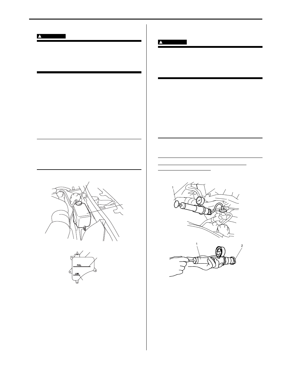
To check level, lift hood and look at “see-through”
coolant reservoir.
It is not necessary to remove radiator cap to check
coolant level.
When engine is cool, check coolant level in reservoir (1).
A normal coolant level should be between “FULL” mark
(2) and “LOW” mark (3) on reservoir (1).
If coolant level is below “LOW” mark (3), remove
reservoir cap (4) and add proper coolant to reservoir to
bring coolant level up to “FULL” mark (2).
NOTE
If proper quality antifreeze is used, there is
no need to add extra inhibitors or additives
that claim to improve system. They may be
harmful to proper operation of system, and
are unnecessary expense.
Engine Cooling System Inspection and
Cleaning
S6JB0B1606003
WARNING
!
To help avoid danger of being burned, do not
remove radiator cap while engine and
radiator are still hot. Scalding fluid and steam
can be blown out under pressure if cap is
taken off too soon.
1) Check cooling system for leakage or damage.
2) Wash radiator cap and filler neck with clean water by
removing radiator cap when engine is cold.
3) Check coolant for proper level and freeze protection.
4) Using a pressure tester (1), check system and
radiator cap (2) for proper pressure holding capacity.
If replacement of cap is required, use a proper cap
for this vehicle.
NOTE
After installing radiator cap to water outlet
cap, make sure that the ear of cap lines is
parallel to radiator.
Cooling system and radiator cap holding
pressure (for inspection)
110 kPa (1.1 kg/cm
2
, 15.6 psi)
5) Tighten hose clamps and inspect all hoses. Replace
hoses whenever cracked, swollen or otherwise
deteriorated.
6) Clean frontal area of radiator core.
4
1
2
3
4
1
I6JB01160004-02
I6JB01160005-01
Нет комментариевНе стесняйтесь поделиться с нами вашим ценным мнением.
Текст