Suzuki Grand Vitara JB627. Manual — part 191
4F-3 Electronic Stability Program:
ESP
® Hydraulic Unit / Control Module
Assembly Description
S6JB0B4601002
ESP
® control module is a component of ESP® hydraulic
unit / control module assembly and has the following
functions.
Self-Diagnosis Function
ESP
® control module monitors each input and output
signals. When ESP
® control module detects any
malfunction, some of ABS warning light (1), EBD
warning light (brake warning light) (2), ESP
® warning
light (3), SLIP indicator light (4), ESP
® OFF light (5) are
turned ON and indicate the abnormality to driver.
• When ignition switch is turned ON, ABS warning, EBD
warning, ESP
® warning, SLIP indicator and ESP®
OFF light for 2 seconds to check its circuit.
• When no abnormality is detected (the system is in
good condition), ABS warning, EBD warning, ESP
®
warning, SLIP indicator and ESP
® OFF turn OFF
after 2 seconds.
• When an abnormality in the system is detected, some
of ABS warning light, EBD warning light (brake
warning light), ESP
® warning light, SLIP indicator
light and/or ESP
® OFF light are turned ON and the
area where that abnormality lies is stored in the
memory in ESP
® control module.
Fail-Safe Mode
When ESP
® control module detects abnormality, the
system goes into fail-safe mode. And some of functions
of ABS, TCS, stability control system are shut down. For
details of fail safe mode, refer to “Fail-Safe Table”.
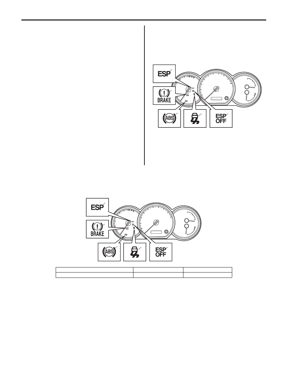
Warning Light, Indicator Light Description
S6JB0B4601003
There are five types of warning light and indicator light in instrument cluster, which are controlled by ESP
® control
module. They give warning / indication to driver by changing the modes light ON / blinking / light OFF.
3
2
1
4
5
I6JB01460002-02
1. ESP
® warning light
3. ABS warning light
5. ESP
® OFF light
2. EBD warning light (brake warning light)
4. SLIP indicator light
1
2
3
4
5
I6JB01460003-02
Electronic Stability Program: 4F-4
The followings are the condition and operation of warning lights and indicator lights.
CAN Communication System Description
S6JB0B4601004
Refer to “CAN Communication System Description in Section 1A” for CAN communication system description. ESP
®
control module communicates control data with each control module as follows.
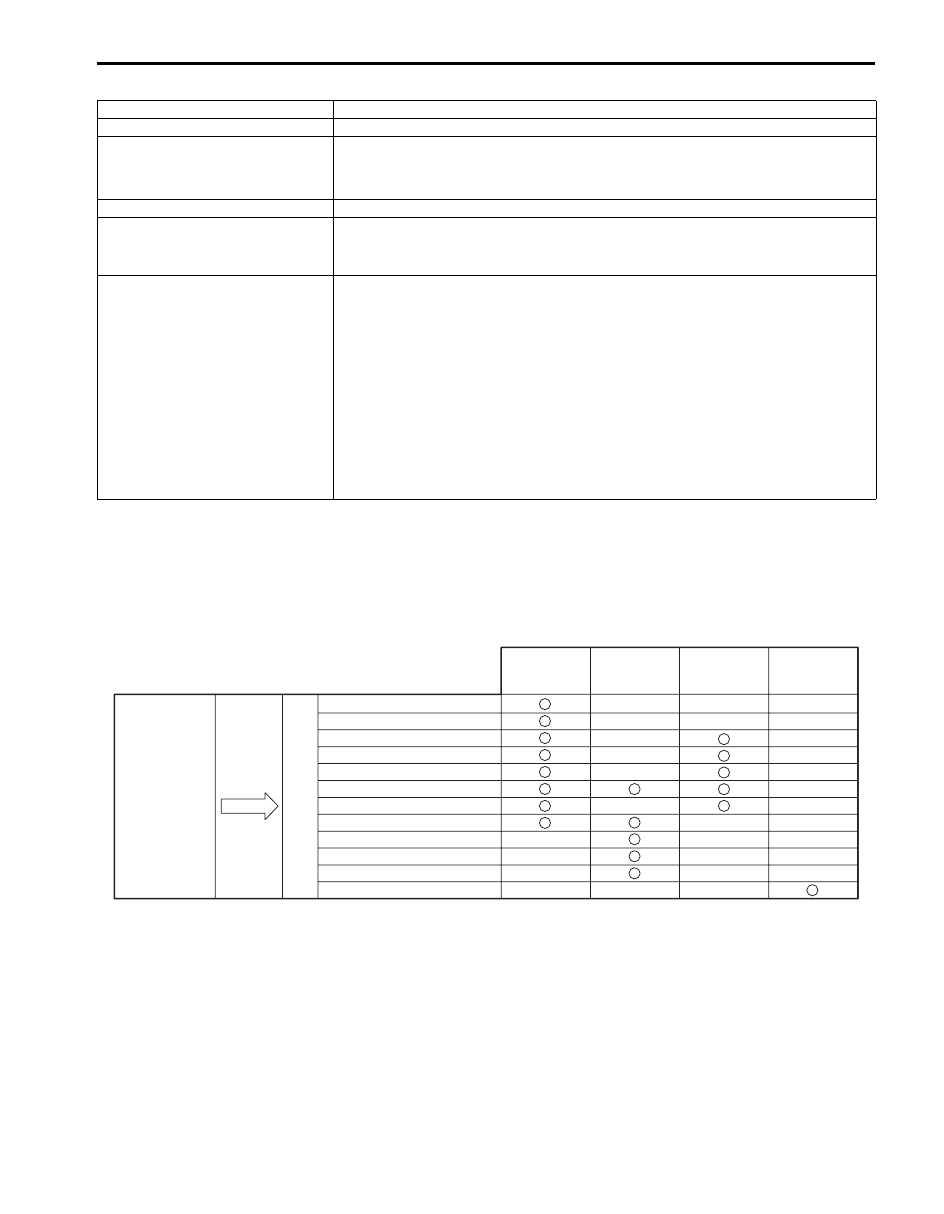
ESP
® Control Module Transmission Data
Warning light / Indicator light
Condition and operation
ABS warning light
If ABS has abnormality, the light turns “ON”.
EBD warning light (brake warning
light)
• If EBD system has abnormality, the light turns “ON”.
• If bake fluid level in reservoir is lower than minimum level, the light turns “ON”.
• Parking brake switch is ON, the light turns “ON”.
ESP
® warning light
If ESP
® systems (other than ABS) has abnormality, the light turns “ON”.
SLIP indicator light
• If stability control system and traction control system is active, the light blinks at
5 Hz.
• If Steering angle sensor calibration is incompleted, the light blinks at 1 Hz.
ESP
® OFF light
• If ESP
® OFF switch is turned “ON”, the ESP® OFF light light up. When it is
“ON”, TCS and stability control system functions are controlled not to work.
However, when the speed is over 30 km/h (18.5 mph), ESP
® OFF light is
turned “OFF” and TCS and stability control system function is back to work
automatically.
• When transfer shift position (if equipped) is in 4L-lock, the ESP
® OFF light light
up to indicate engine torque down and stability control system in TCS are
controlled not to activate to increase the driving force.
However, the brake-traction control works through ESP
® OFF light light up.
• ESP
® OFF light light up to indicate that brake control of traction control
function is controlled not to act if brake pad temperature is over 350
°C (662 °F)
and any of wheel is in wheel spin condition.
Torque up request
Torque down request
Wheel speed signal (front)
Wheel speed signal (rear right)
Wheel speed signal (rear left)
ESP® system (other than ABS) active
ABS active
ESP® OFF indication ON
ESP® indication ON
ABS indication ON
EBD indication ON
Steering angle neutral position
Combination
Meter
Transmit
DATA
ESP® control
module
ECM
4WD control
module
(if equiped)
Steering angle
sensor
I6JB01460004-02
4F-5 Electronic Stability Program:
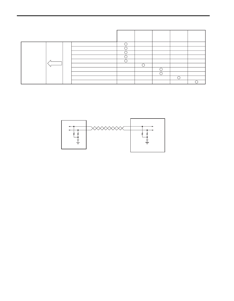
ESP
® Control Module Reception Data
CAN Communication System For Electronic Stability Program Description
S6JB0B4601005
There is CAN communication system only for ESP
® control module (1) and yaw rate / G sensor assembly (2).
This CAN communication system is independent from other control modules.
ESP
® communicates control data with yaw rate / G sensor assembly as follows.
ESP
® Transmission Data to Yaw Rate / G Sensor Assembly
• Longitudinal G neutral position
• Lateral G neutral position
ESP
® Reception Data from Yaw Rate / G Sensor Assembly
• Vehicle yaw rate signal
• Vehicle longitudinal G signal
• Vehicle lateral G signal
• Yaw rate / G sensor assembly related malfunction
Engine torque signal
Accelerator pedal position
Engine speed
Cruise control signal (if equipped)
Brake pedal switch signal
Transmission gear selector position
Brake fluid level switch signal
Parking brake switch signal
4WD shift position (if equipped)
Steering angle signal
Receive
DATA
ESP® control
module
ECM
4WD control
module
(if equiped)
Steering
angle sensor
TCM
(A/T model)
BCM
I6JB0B460001-02
2
1
I6JB01460006-01
Electronic Stability Program: 4F-6
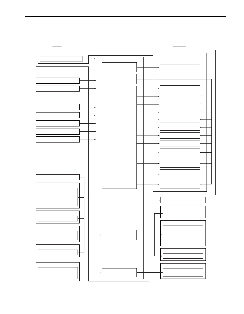
Schematic and Routing Diagram
Electronic Stability Program Schematic
S6JB0B4602001
INPUT
OUTPUT
ESP® control module
Wheel speed sensor (LF)
Wheel speed sensor (LR)
Wheel speed sensor (RF)
Battery Voltage
Master cylinder pressure sensor
Ignition Voltage
Pump motor driver
(transistor)
Solenoid valve power
supply driver (transistor)
Solenoid valve driver
(transistor)
CAN driver
CAN driver (for yaw rate /
G sensor assembly)
Hydraulic unit
Pump motor
LF inlet solenoid valve
LF outlet solenoid valve
LR inlet solenoid valve
LR outlet solenoid valve
RF inlet solenoid valve
RF outlet solenoid valve
RR inlet solenoid valve
RR outlet solenoid valve
Data link connector
Data link connector
ESP® hydraulic unit/control module assembly
Wheel speed sensor (RR)
Brake lignt switch
Engine torque
Accelerator pedal position
Engine speed
Cruise control (if equipped)
Master cylinder cut solenoid
valve No. 1
Master cylinder cut solenoid
valve No. 2
Low pressure solenoid valve
No. 1
Low pressure solenoid valve
No. 2
ECM
Brake fluid level switch
Parking brake switch
BCM
Steering angle sensor
ESP® OFF switch
Yaw rate
Longitudinal G
Lateral G
Yaw rate / G sensor assembly
Gear selector position
TCM (A/T model)
Gear selector position
4WD control module
ABS warning lamp
EBD warning lamp
ESP® warning lamp
SLIP indicator lamp
ESP® OFF lamp
Combination meter
Torque request
ECM
Steering angle neutral position
Steering angle sensor
Longitudial G neutral position
Lateral G neutral position
Yaw rate / G sensor assembly
I6JB0B460002-04
Нет комментариевНе стесняйтесь поделиться с нами вашим ценным мнением.
Текст