Suzuki Grand Vitara JB627. Manual — part 192
4F-7 Electronic Stability Program:
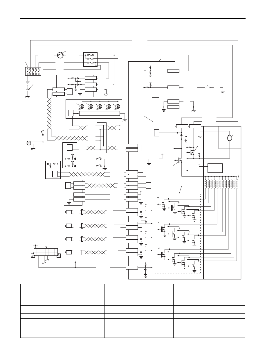
Electronic Stability Program Wiring Circuit Diagram
S6JB0B4602002
WHT/RED
WHT/GRN
BLK/YEL
WHT/RED
M
12V
GRN/ORN
1
2
3
13
12V
5V
12V
VCC
WHT/BLU
WHT/BLU
PPL/WHT
+BB
PPL/RED
WHT
BLK
WHT
BLK
WHT
BLU/BLK
GRN/BLK
BLU
GRN
YEL/BLK
YEL
LT GRN
LT GRN/BLK
E53-15
E53-14
E53-2
E53-3
E53-6
E53-5
E53-11
E53-12
E53-35
E53-33
E53-1
E53-32
RED/BLK
E53-13
E53-44
RED
WHT
RED
WHT
WHT/RED
WHT/BLU
E53-42
E53-46
RED
12V
12V
12V
12V
12V
BLK
WHT
BLK
WHT
7
9
12V
12V
RED/BLK
WHT
WHT
GRN/ORN
G45-3
G45-1
BLK
G45-2
G45-9
G45-10
RED
GRN/WHT
GRN
E53-29
E53-25
E53-37
E53-31
L39-3
L39-5
BLK
WHT
L39-2
L39-1
12V
PNK/GRN
PNK/WHT
E53-16
E53-47
BLK
BLK
5V
BLU/WHT
BLK
12V
E53-7
WHT
4
5
6
6
8
10
11
12
14
16
17
6
19
18
6
22
23
24
25
26
27
29
28
30
33
37
39
32
36
38
35
34
6
23
15
20
21
31
I6JB0B460004-01
1. Battery
14. Junction connector
27. Right-rear wheel speed sensor
2. Main fuse box
15. To TCM, 4WD control module and keyless
start control module
28. Data link connector
3. Ignition switch
16. Brake light switch
29. To ECM, TCM, SDM, BCM and 4WD control
module
4. Junction block assembly
17. Brake light
30. ESP
® hydraulic unit / control module
assembly
5. Steering angle sensor
18. ECM
31. Solenoid valve driver (transistor)
6. CAN driver
19. BCM
32. Master cylinder pressure sensor
7. Combination meter
20. Brake fluid level switch
33. ESP
® OFF switch
8. SLIP indicator light
21. Parking brake switch
34. Power control unit
9. ESP
® OFF light
22. Yaw rate / G sensor assembly
35. Internal memory

Electronic Stability Program: 4F-8
Terminal Arrangement of ESP
® Control Module Connector (Viewed from Terminal Side)
10. ESP
® warning light
23. CAN driver (for yaw rate / G sensor
assembly)
36. Pump motor driver (transistor)
11. ABS warning light
24. Left-front wheel speed sensor
37. Pump motor
12. EBD warning light (brake warning light)
25. Right-front wheel speed sensor
38. Solenoid valve power supply driver
(transistor)
13. Light driver module
26. Left-rear wheel speed sensor
39. Solenoid valves
Terminal
Circuit
Terminal
Circuit
E53-1
Solenoid valve power supply driver
(transistor)
E53-25
CAN communication line (low) for yaw
rate / G sensor assembly
E53-2
Right-front wheel speed sensor (–)
E53-26
—
E53-3
Right-front wheel speed sensor (+)
E53-27
—
E53-4
—
E53-28
—
E53-5
Left-rear wheel speed sensor (+)
E53-29
CAN communication line (high) for yaw
rate / G sensor assembly
E53-6
Left-rear wheel speed sensor (–)
E53-30
—
E53-7
Fluid pressure switch signal
E53-31
Ground for yaw rate / G sensor assembly
E53-8
—
E53-32
Pump motor driver (transistor)
E53-9
—
E53-33
Data link connector
E53-10
—
E53-34
—
E53-11
Right-rear wheel speed sensor (–)
E53-35
Ignition switch
E53-12
Right-rear wheel speed sensor (+)
E53-36
—
E53-13
CAN communication line (high)
E53-37
Power source for yaw rate / G sensor
assembly
E53-14
Left-front wheel speed sensor (+)
E53-38
—
E53-15
Left-front wheel speed sensor (–)
E53-39
—
E53-16
Ground
E53-40
—
E53-17
—
E53-41
—
E53-18
—
E53-42
CAN communication line (high) for ECM
E53-19
—
E53-43
—
E53-20
—
E53-44
CAN communication line (low)
E53-21
—
E53-45
—
E53-22
—
E53-46
CAN communication line (low) for ECM
E53-23
—
E53-47
Ground
E53-24
—
E53
16
1
15
2
3
4
5
6
7
8
9
10
11
12
13
14
17
18
19
20
21
22
23
24
25
26
27
28
29
30
31
32
33
34
35
36
37
38
39
40
41
42
43
44
45
46
47
I6JB01460009-02
4F-9 Electronic Stability Program:
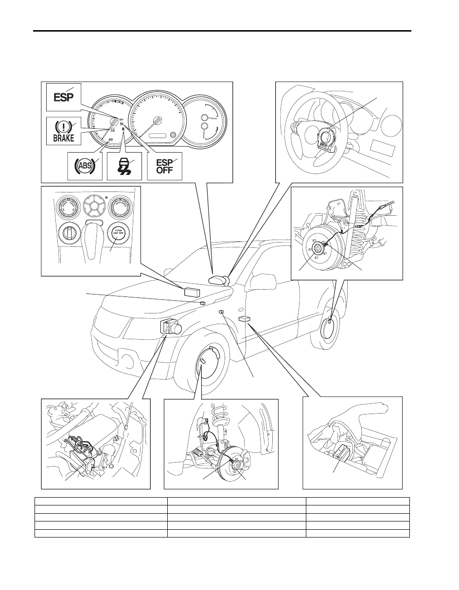
Component Location
Electronic Stability Program Component Location
S6JB0B4603001
1
2
3
4
5
7
6
9
8
14
16
10
11
12
13
I6JB0B460005-02
1. ESP
® warning light
6. Steering angle sensor
11. Front wheel speed sensor
2. EBD warning light (brake warning light)
7. ESP
® OFF switch
12. Front wheel encoder
3. ABS warning light
8. Rear wheel speed sensor
13. Yaw rate / G sensor assembly
4. SLIP indicator light
9. Rear wheel encoder
14. Data link connector
5. ESP
® OFF light
10. ESP
® hydraulic unit / control module assembly
15. Brake light switch

Electronic Stability Program: 4F-10
Diagnostic Information and Procedures
Electronic Stability Program Check
S6JB0B4604001
Refer to the following items for the details of each step.
Step
Action
Yes
No
1
Malfunction analysis
1) Perform “Customer complaint analysis: ”.
2) Perform “Problem symptom confirmation: ”.
3) Perform “DTC check, record and clearance: ” and
recheck DTC.
Is there any malfunction DTC?
Go to Step 4.
Go to Step 2.
2
Driving test
1) Perform “Step 2: Driving Test: ”.
Is trouble symptom identified?
Go to Step 3.
Go to Step 6.
3
DTC check
1) Perform “DTC Check”.
Is it malfunction code?
Go to Step 4.
Go to Step 5.
4
® check
1) Inspect and repair referring to applicable DTC flow.
Does trouble recur?
Go to Step 5.
Go to Step 7.
5
Brakes diagnosis
1) Inspect and repair referring to “Brakes Symptom
Does trouble recur?
Go to Step 3.
Go to Step 7.
6
Check for intermittent problem
1) Check intermittent troubles referring to “Intermittent and
Poor Connection Inspection in Section 00” and related
circuit of trouble code recorded in Step 1.
Does trouble recur?
Go to Step 4.
Go to Step 7.
7
Final confirmation test
1) Perform “Step 7: Final Confirmation Test: ”.
Does trouble recur?
Go to Step 3.
End.
Нет комментариевНе стесняйтесь поделиться с нами вашим ценным мнением.
Текст