Suzuki Grand Vitara JB627. Manual — part 216
5A-48 Automatic Transmission/Transaxle:
DTC Troubleshooting
DTC P0717: Input / Turbine Speed Sensor Circuit No Signal
S6JB0B5104025
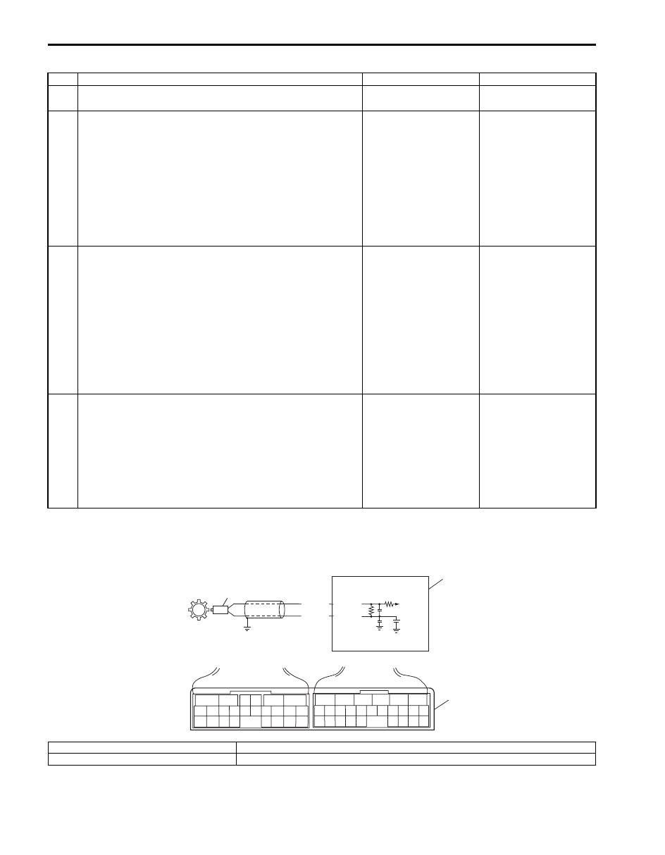
Wiring Diagram
Step
Action
Yes
No
1
Was “A/T System Check” performed?
Go to Step 2.
Go to “A/T System
Check”.
2
Check transmission fluid temperature sensor A circuit
for open
1) Turn ignition switch OFF.
2) Disconnect TCM connectors from TCM.
3) Check for proper connection to transmission fluid
temperature sensor A at terminal “E92-11” and “E92-12”.
4) If OK, check continuity between terminal “E92-11” and
“E92-12” of disconnected harness side TCM connector.
Is continuity indicated?
Go to Step 3.
Transmission fluid
temperature sensor A
signal or ground, circuit
is open circuit. If circuit
is OK, go to Step 4.
3
Check transmission fluid temperature sensor A circuit
for IG short
1) Cool down A/T fluid temperature under ambient
temperature.
2) Connect TCM connectors to TCM with ignition switch
OFF.
3) Turn ignition switch ON.
4) Measure voltage between terminal “E92-11” of TCM
connector and ground.
Is it 4.89 V or more?
“Transmission fluid
temperature sensor A
signal” circuit shorted to
power supply circuit. If
circuit is OK, go to Step
4.
Intermittent trouble or
faulty TCM. Check for
intermittent trouble
referring to “Intermittent
and Poor Connection
Inspection in Section
00”. If OK, substitute a
known-good TCM and
recheck.
4
Inspection transmission fluid temperature sensor A
1) Inspection transmission fluid temperature sensor A
referring to “Transmission Fluid Temperature Sensor
Removal and Installation”.
Is check result satisfactory?
Intermittent trouble or
faulty TCM. Check for
intermittent trouble
referring to “Intermittent
and Poor Connection
Inspection in Section
00”. If OK, substitute a
known-good TCM and
recheck.
Replace valve body
harness including
transmission fluid
temperature sensor A
referring to
“Transmission Fluid
Temperature Sensor
Removal and
Installation”
BLU
PNK
1
2
2.5V
E93-6
E93-16
6
5
16 15 14 13 12 11
4 3
24 23
21
22
10 9
8
7
2
1
19
20
18 17
E92
17 16
26 25
15 14
6
5
3
4
2
13 12
23 22
24
11 10 9
21 20 19
8 7
18
1
E93
3
I5JB0A510022-01
1. TCM
3. Terminal arrangement of TCM connector (viewed from harness side)
2. Input shaft speed sensor

Automatic Transmission/Transaxle: 5A-49
DTC Detecting Condition and Trouble Area
DTC Confirmation Procedure
1) Connect scan tool to DLC with ignition switch OFF.
2) Clear DTCs in TCM and ECM memories by using scan tool.
3) Start engine and shift select lever to “D” range.
4) Start vehicle and increase vehicle speed to about 40 km/h (25 mile/h) for 3 minutes or more.
5) Stop vehicle.
6) Check DTC, pending DTC and freeze-frame data.
DTC Troubleshooting
DTC Detecting Condition
Trouble Area
No pulse signal of input shaft speed sensor is inputted for 5
pulses period of output shaft speed sensor through it is
detected more than 600 rpm.
(1 driving cycle detection logic)
• Input shaft speed sensor or its circuit malfunction.
• Improper input shaft speed sensor installation.
• Damaged clutch drum.
• Foreign material attachment to sensor or drum.
• TCM
Step
Action
Yes
No
1
Was “A/T System Check” performed?
Go to Step 2.
Go to “A/T System
Check”
2
Check input shaft speed sensor circuit
1) Disconnect TCM connectors with ignition switch OFF.
2) Check for proper connection to input shaft speed sensor
at “E93-6” and “E93-16” terminals.
3) If OK, check resistance of sensor circuit.
Resistance of input shaft speed sensor circuit
Between terminals “E93-6” and “E93-16” of
disconnected harness side TCM connector: 560 –
680
Ω at 20 °C (68 °F)
Between terminals “E93-16” of disconnected
harness side TCM connector and ground: No
continuity
Are check results satisfactory?
Go to Step 4.
Go to Step 3.
3
Inspection input shaft speed sensor
Inspect input shaft speed sensor referring to “Input Shaft
Speed Sensor Inspection”.
Is check result satisfactory?
Input shaft speed
sensor signal or ground
circuit is malfunction.
Go to Step 4.
4
Check visually input shaft speed sensor and clutch
drum using mirror for following
• No damage
• No foreign material attached
• Correct installation
Are they in good condition?
Intermittent trouble.
Check for intermittent
trouble referring to
“Intermittent and Poor
Connection Inspection
in Section 00”.
Clean, repair or replace.
I2RH01510023-01
5A-50 Automatic Transmission/Transaxle:
DTC P0722: Output Speed Sensor Circuit No Signal
S6JB0B5104026
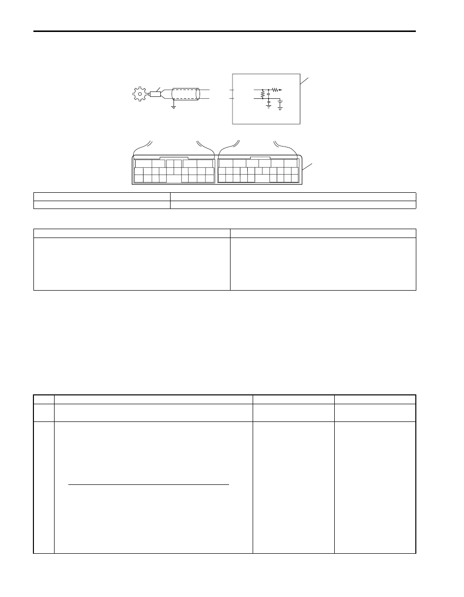
Wiring Diagram
DTC Detecting Condition and Trouble Area
DTC Confirmation Procedure
1) Connect scan tool to DLC with ignition switch OFF.
2) Clear DTCs in TCM and ECM memories by using scan tool.
3) Start engine and shift select lever to “D” range.
4) Start vehicle and increase vehicle speed to about 80 km/h (50 mile/h) for 2 minutes or more.
5) Stop vehicle.
6) Check DTC, pending DTC and freeze-frame data.
DTC Troubleshooting
2.5V
ORN
WHT
2
1
E93-5
E93-14
6
5
16 15 14 13 12 11
4 3
24 23
21
22
10 9
8
7
2
1
19
20
18 17
E92
17 16
26 25
15 14
6
5
3
4
2
13 12
23 22
24
11 10 9
21 20 19
8 7
18
1
E93
3
I5JB0A510023-01
1. TCM
3. Terminal arrangement of TCM connector (viewed from harness side)
2. Output shaft speed sensor
DTC Detecting Condition
Trouble Area
No pulse signal of output shaft speed sensor is inputted for
18 pulses period of input shaft speed sensor.
(1 driving cycle detection logic)
• Output shaft speed sensor or its circuit malfunction.
• Improper output shaft speed sensor installation.
• Damaged sensor rotor.
• Foreign material attachment to sensor or rotor.
• TCM
Step
Action
Yes
No
1
Was “A/T System Check” performed?
Go to Step 2.
Go to “A/T System
Check”.
2
Check input shaft speed sensor circuit
1) Disconnect TCM connectors with ignition switch OFF.
2) Check for proper connection to input shaft speed sensor
at “E93-5” and “E93-14” terminals.
3) If OK, check resistance of sensor circuit.
Resistance of input shaft speed sensor circuit
Between terminals “E93-5” and “E93-14” of
disconnected harness side TCM connector: 560 –
680
Ω at 20 °C (68 °F)
Between terminals “E93-14” of disconnected
harness side TCM connector and ground: No
continuity
Are check results satisfactory?
Go to Step 4.
Go to Step 3.
Automatic Transmission/Transaxle: 5A-51
DTC P0741 / P0742: TCC Circuit Performance or Stuck OFF / TCC Circuit Stuck ON
S6JB0B5104027
DTC Detecting Condition and Trouble Area
DTC Confirmation Procedure
WARNING
!
• When performing a road test, select a place where there is no traffic or possibility of a traffic
accident and be very careful during testing to avoid occurrence of an accident.
• Road test should be carried out with 2 persons, a driver and tester, on a level road.
1) Connect scan tool to DLC with ignition switch OFF.
2) Clear DTCs in TCM and ECM memories by using scan tool.
3) Start engine and warm it up to normal operating temperature.
4) Shift select lever to “N” and “D” range for each 10 seconds.
5) Drive vehicle with 5th in “D” range and lock-up ON for 20 seconds or longer referring to “Automatic Gear Shift
6) Drive vehicle with 2nd or 3rd gear in “D” range, 15 – 20% throttle opening and at vehicle speed of 40 km/h (25
mile/h).
7) Stop vehicle and turn ignition switch OFF.
8) Repeat Step 3) to 6) one time.
9) Stop vehicle.
10) Check DTC, pending DTC and freeze-frame data.
3
Inspection output shaft speed sensor
Inspect input shaft speed sensor referring to “Output Shaft
Speed Sensor Inspection”.
Is check result satisfactory?
Output shaft speed
sensor signal or ground
circuit is malfunction.
Go to Step 4.
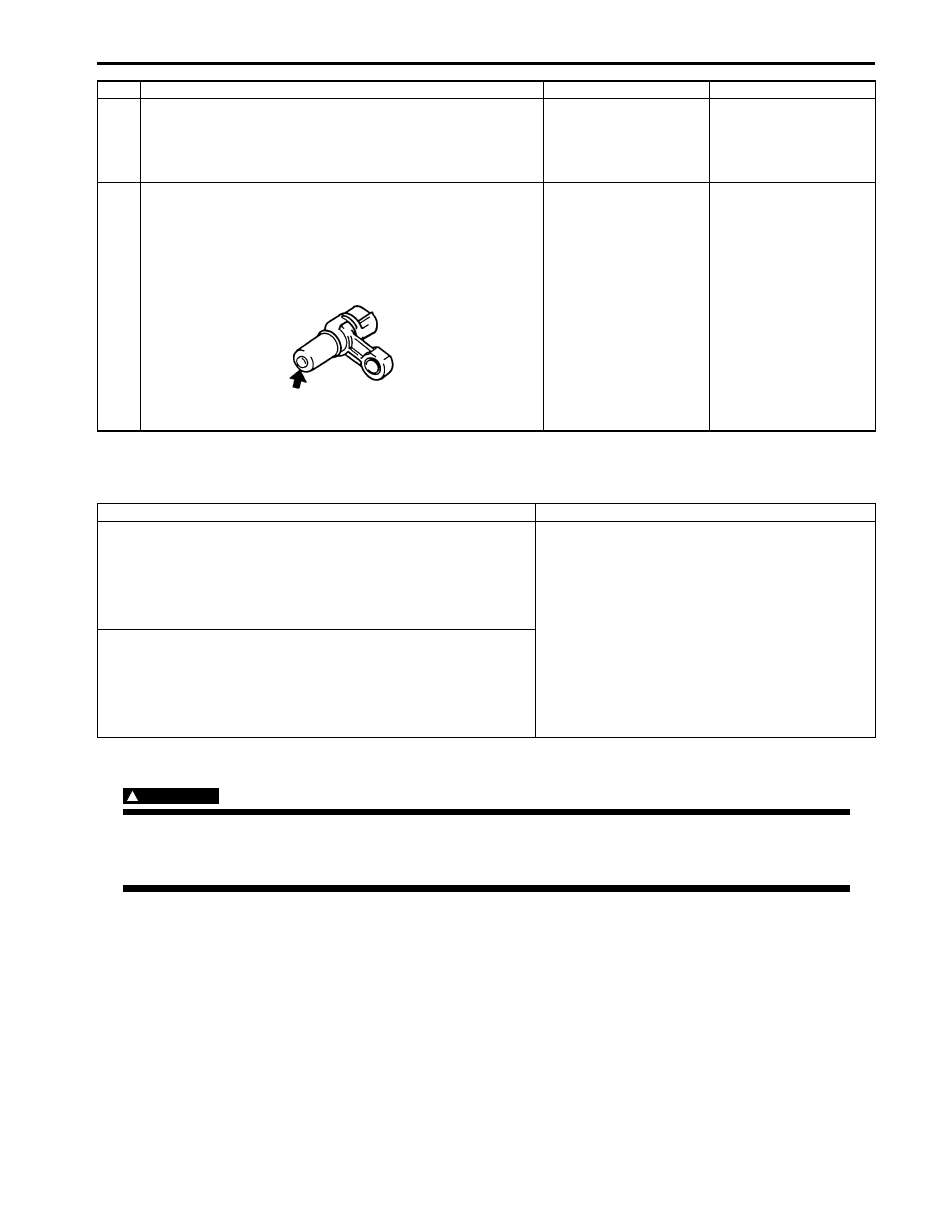
4
Check visually Output shaft speed sensor and sensor
rotor using mirror for following
• No damage
• No foreign material attached
• Correct installation
Are they in good condition?
Intermittent trouble.
Check for intermittent
trouble referring to
“Intermittent and Poor
Connection Inspection
in Section 00”.
Clean, repair or replace.
Step
Action
Yes
No
I2RH01510023-01
DTC Detecting Condition
Trouble Area
DTC P0741:
When driving vehicle with 4th or 5th gear in “D” range, difference
in revolution between engine and A/T input (input shaft speed) is
larger than specification although TCM commanded TCC
solenoid to turn ON.
(2 driving cycle detection logic)
• Mechanical malfunction of TCC solenoid valve.
• Malfunction of valve body assembly.
• Fluid passage clogged or leaking.
• Torque converter clutch malfunction.
DTC P0742:
When driving vehicle with 2nd, 3rd, 4th or 5th gear in “D” range,
difference in revolution between engine and A/T input (input shaft
speed) is smaller than specification although TCM commanded
TCC solenoid to turn OFF.
(2 driving cycle detection logic)
Нет комментариевНе стесняйтесь поделиться с нами вашим ценным мнением.
Текст