Suzuki Grand Vitara JB627. Manual — part 413
10B-1 Body Electrical Control System:
Control Systems
Body Electrical Control System
Precautions
Precautions in Diagnosing Trouble
S6JB0BA200001
• Diagnostic information stored in BCM memory can be cleared as well as checked by using SUZUKI scan tool.
Before using scan tool, read its Operator’s (Instruction) Manual carefully to have good understanding as to what
functions are available and how to use it.
• Be sure to read “Precautions for Electrical Circuit Service in Section 00” before inspection and observe what is
written there.
• Communication of ECM, TCM (if equipped), BCM, ABS or ESP
® control module (if equipped), 4WD control module
(if equipped), keyless start control module (if equipped), steering angle sensor (if equipped) and combination meter
is established by CAN (Controller Area Network).
Therefore, be sure to read “Precaution for CAN Communication System in Section 00” before inspection and handle
CAN communication line.
General Description
BCM General Description
S6JB0BA201001
The BCM incorporates relays and controllers which are used for the following systems and controls them.
• Power door lock (if equipped)
• Keyless entry (if equipped)
• Door lock function of keyless start system (if equipped)
• Rear wiper
• Combination meter
• Interior light / luggage room light
• Warning buzzer
• Rear end door window defogger and door mirror heater (if equipped)
• DRL (if equipped)
• Auto-on headlight (if equipped)
• Front fog light (if equipped)
• Theft deterrent light
• Clearance light
Also, the BCM has a function to cause the interior light and open door warning light in the combination meter to turn off
when any door is left open for longer than 15 minutes to reduce wasteful battery consumption.
In addition, it is possible to check operation of actuator which is controlled by BCM by using the output test function of
SUZUKI scan tool to operate actuator simulatively.
Body Electrical Control System: 10B-2
CAN Communication System Description
S6JB0BA201002
Refer to “CAN Communication System Description in Section 1A” for CAN communication system description. BCM
communication control data with each control module as follows.
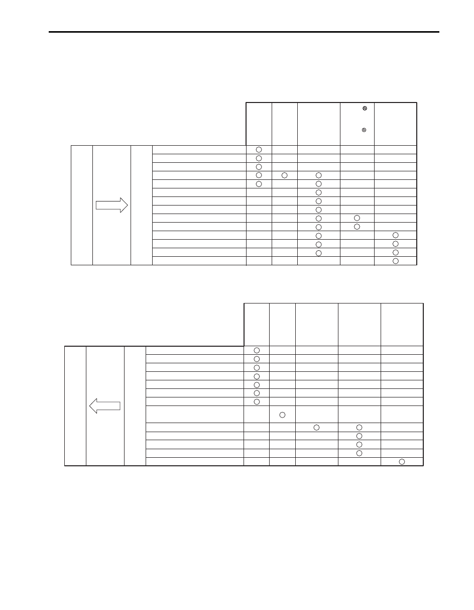
BCM Transmission Data
BCM Reception Data
ECM
Combination
Meter
Transmit
DATA
BCM
Keyless
Start
Control
Module
(if equipped)
TCM
(A/T
model)
ESP
Control
Module
(ESP
model)
A/C switch ON signal
Blower fan signal
A/T mode status signal
Electric load signal
DRL ON signal
Illumination ON signal
Diagnostic trouble code (DTC)
Seat belt buckle switch signal
Charging system signal
Engine oil pressure switch signal
Brake fluid level switch signal
Parking brake switch signal
Door switch status
Door lock status
I6JB0BA20001-02
Engine speed signal
Engine coolant temperature signal
Vehicle speed signal
Brake pedal switch signal
A/C compressor clutch signal
A/C refrigerant pressure signal
Fuel consumption signal
Transmission range sensor signal
(A/T select lever position)
Buzzer request signal
Door lock/unlock request signal
Ignition knob switch signal
Answer back request signal
Fuel level percent signal
TCM
(A/T
model)
ECM
4WD
Control
Module
(if equipped)
Keyless
Start
Control
Module
(if equipped)
DATA
BCM
Receive
Combination
Meter
I6JB0BA20002-02
10B-3 Body Electrical Control System:
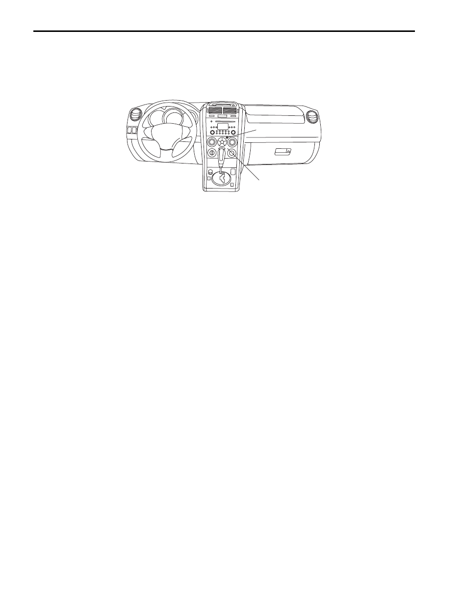
Theft Deterrent Light Description
S6JB0BA201003
Theft deterrent light (2) is installed on the HVAC control module (1) for the theft preventive purpose.
The BCM makes the theft deterrent light flash at certain intervals after the ignition switch is turned off until it is turned
on again. Also, DTCs stored in BCM can be checked by reading the flashing patterns of the theft deterrent light when
diagnosing troubles.
2
1
I5JB0AA20001-01
Body Electrical Control System: 10B-4
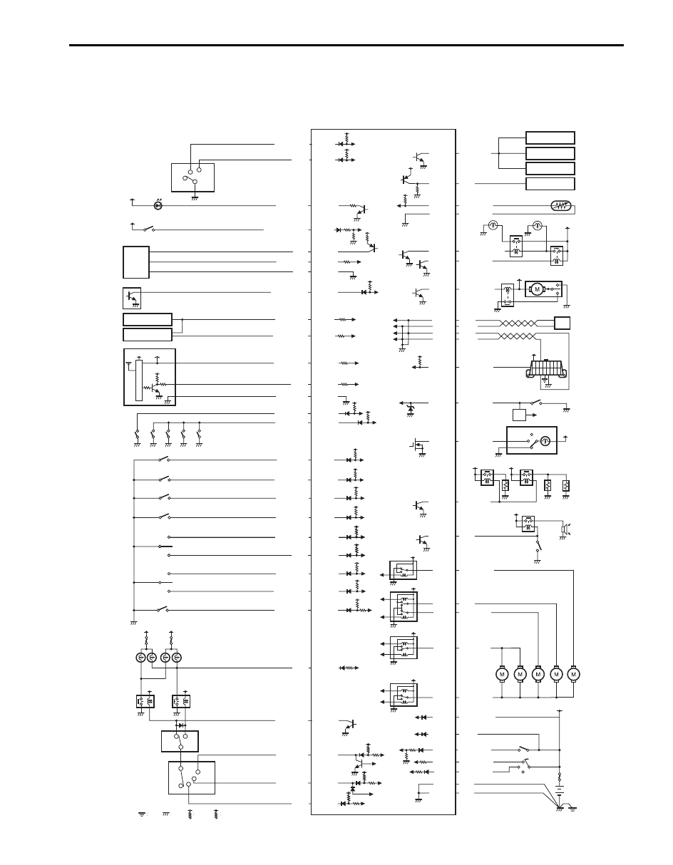
Schematic and Routing Diagram
Body Electrical Control System Wiring Circuit Diagram
S6JB0BA202001
RED/BLK
PPL/GRN
PNK/BLK
PNK/GRN
RED/BLK
RED
WHT
WHT/BLK
IG1
PNK/BLK
YEL/BLK
YEL/RED
YEL/GRN
BRN
YEL/BLK
BLK/ORN
BLK/RED
IG1
G31-1
G31-3
PPL/WHT
ON
DOOR
OFF
BLK/RED
G32-15
YEL/RED
G31-34
+B
+B
+B
RED/BLU
G31-12
G31-13
+B
YEL
G30-19
BLU/BLK
G30-22
+B
+B
BLU
G31-15
BLU/BLK
G31-14
BLK/RED
G31-35
PNK/BLU
PNK/BLU
PNK
G32-2 BLU/YEL
G32-8 BLU
G32-9 BLU/BLK
G32-3 BLU/RED
+B
+B
+B
G32-7 BLU/WHT
+B
ORN/BLU
G31-2
G31-4
LT GRN/RED
G31-17
YEL
BLK
PNK/GRN
+BB
PNK/BLU
GRN/YEL
G31-8
G31-7
G31-40
G31-27
G31-26
G31-24
G31-9
G31-39
G31-38
G31-18
G31-19
G31-20
G30-9
G30-16
G30-5
G30-4
G31-21
G31-36
G31-37
G31-28
G31-22
G31-23
G31-10
LT GRN/BLK
WHT/RED
RED
WHT
1
22
24
55
40
6
25
26
4
3
27
30
38
37
50
39
41
28
42
53
54
44
45
46
33
33
33
33
36
36
35
34
29
48
49
51
32
31
43
37
52
5 V
12 V
23
20
19
18
17
16
9
13
14
14
14
14
12
15
11
10
21
8
2
7
5
GRN
GRN/RED
ON
INT
OFF
G30-7
G30-6
G30-21
G30-11
RED/BLU
+B
HI
LO
C
H
A
+B
+B
+B
RED G32-12
RED/BLU G31-16
GRY
PNK/BLU G30-10
BLK
G32-1
G30-12
+B
PPL/RED
G30-1
BLK
WHT/BLK
G30-2
G32-5 RED/WHT
G30-3 BLU/RED
G32-13 WHT
G31-25
I6JB0BA20003-01
Нет комментариевНе стесняйтесь поделиться с нами вашим ценным мнением.
Текст