Suzuki Grand Vitara JB627. Manual — part 160
3C-44 Transfer:
DTC C1246: Clutch Pedal Position (CPP) Switch Circuit Short
S6JB0B3304025
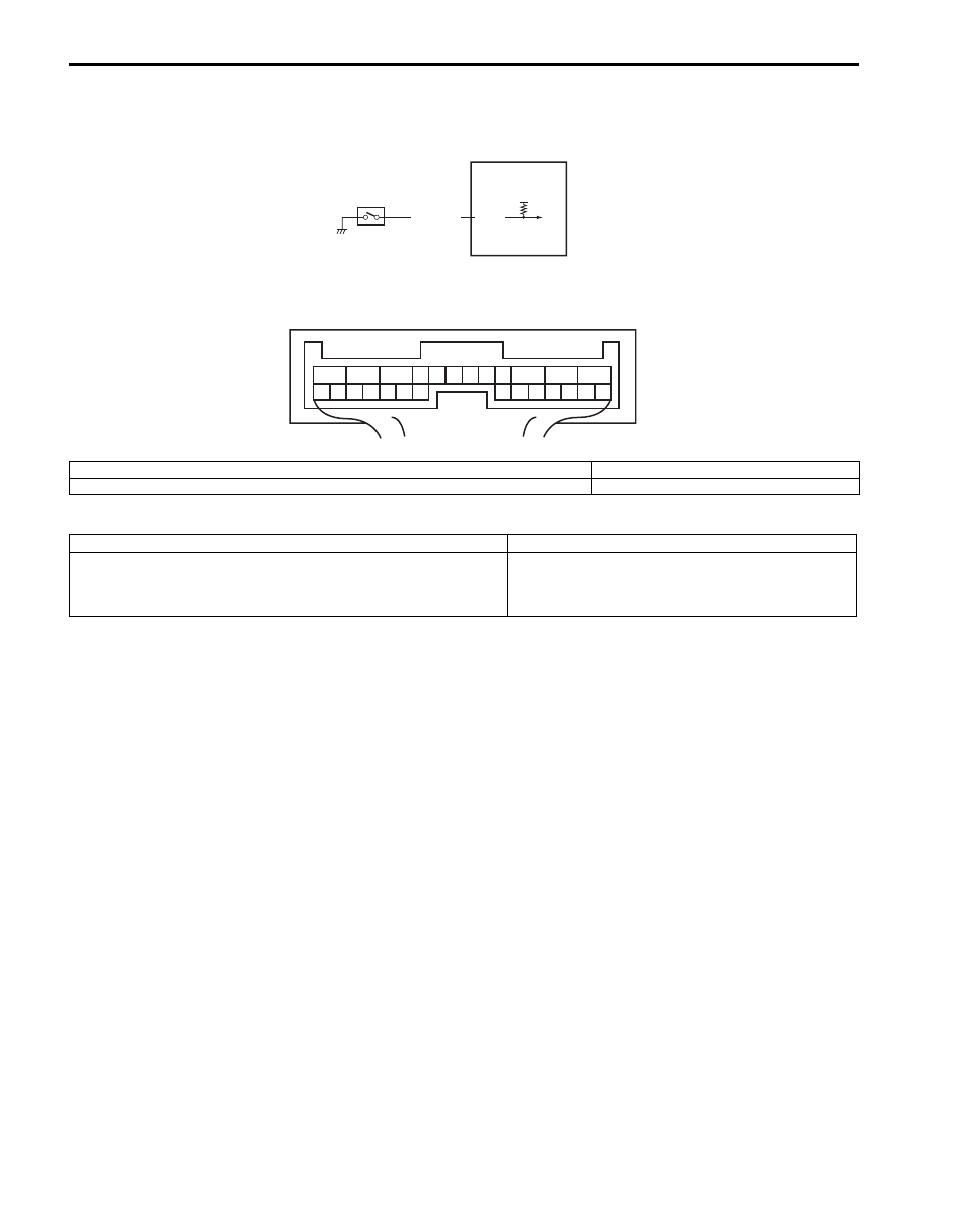
Wiring Diagram
DTC Detecting Condition and Trouble Area
DTC Confirmation Procedure
1) Clear DTC using scan tool.
2) Start engine and drive vehicle at 50 km/h (31 mile/h) or more vehicle speed at least for 1 min.
3) Stop vehicle and check DTC.
12V
E91-7
BLK/ORN
1
2
1
2
3
4
5
6
7
8
9
10
11
12
13
14
15
16
17
18
19
20
21
22
23
24
25
26
[A]
I5JB0A332020-01
[A]: 4WD control module connector “E91” (viewed from harness side)
2. 4WD control module
1. CPP switch
DTC detecting condition
Trouble area
CPP switch signal is input when vehicle speed is 30 km/h (19
mph).
• CPP switch
• CPP switch circuit
• 4WD control module

Transfer: 3C-45
Troubleshooting
Step
Action
Yes
No
1
Was “4WD control system check” performed?
Go to Step 2.
Go to “4WD Control
System Check”.
2
CPP switch circuit check
1) Disconnect CPP switch connector with ignition switch
OFF.
2) Check for proper connection to terminal of CPP switch
connector.
3) If connection is OK, measure voltage between “BLK/
ORN” terminal of CPP switch connector and vehicle
body ground with ignition switch ON.
Is it 10 – 14 V?
Go to Step 3.
Go to Step 4.
3
CPP switch check
1) Check CPP switch referring to “Clutch Pedal Position
(CPP) Switch Inspection and Adjustment in Section 5C”.
Is switch in good condition?
Substitute a known-
good 4WD control
module and recheck.
Replace CPP switch.
4
Wire harness check
1) Disconnect connector from 4WD control module
connector “E91” with ignition switch OFF.
2) Check for proper connection to “E91-7” terminal of 4WD
control module connector.
3) If OK, measure resistance between “BLK/ORN” terminal
of CPP switch connector and “E91-7” terminal of 4WD
control module connector.
Is it 1 M
Ω
or more?
Substitute a known-
good 4WD control
module and recheck.
“BLK/ORN” wire is
shorted to ground
circuit.
3C-46 Transfer:
DTC U1073: Control Module Communication Bus Off
S6JB0B3304026
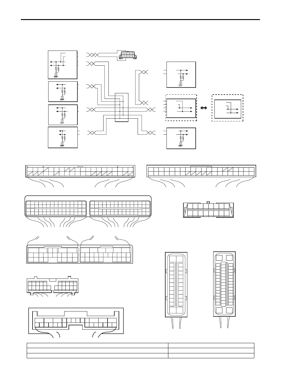
Wiring Diagram
WHT
RED
WHT
RED
G44-18
G44-19
G44
[A]
[B]
[C]
[G]
1
2
3
4
5
6
7
8
9
10
11
14
15
16
36
34 33 32 31 30 29
24 23
37
18
19
20
G28-8
G28-10
WHT/BLU
WHT/BLU
WHT/RED
WHT/RED
E23-4
E23-19
WHT
RED
E03-12
E03-10
E03-6
E03-8
WHT
RED
E92-17
E92-7
WHT
RED
E91-22
E91-23
WHT
RED
G31-1
G31-3
6
5
16 15 14 13 12 11
4 3
24 23
21
22
10 9
8
7
2
1
19
20
18 17
E92
17 16
26 25
15 14
6
5
3
4
2
13 12
23 22
24
11 10 9
21 20 19
8 7
18
1
E93
2 1
E23
C37
3
4
18
19
5
6
7
10
11
17
20
47 46
49
50
51
21
22
52
16
25
9
24
14
29
55
57
5453
59
60
58
2
26
27
28
15
30
56
48
32 31
34
35
36
37
40
42
3938
44
45
43
41
33
1
12
13
23
8
3
4
18
19
5
6
7
10
11
17
20
47 46
49
50
51
21
22
52
16
25
9
24
14
29
55
57
5453
59
60
58
26
27
28
15
30
56
48
32 31
34
35
36
37
40
42
3938
44
45
43
41
33
12
13
23
8
1
2
3
4
5
6
7
8
9
10
11
17
1615141312
2221201918
G28
[E]
G31
1
2
3
4
7
8
9
10
11
14
15
16
36
34
35
24 23
21
22
28 27
25
26
37
39 38
40
18 17
13 12
19
20
[D]
E03
15
16
17
18
19
20
21
22
23
24
25
2
3
4
5
6
7
8
9
10
11
12
1
13
14
26
1
2
3
4
5
6
7
8
9
10
11
12
13
14
15
16
17
18
19
20
21
22
23
24
25
26
[F]
E91
WHT
RED
G31-2
G31-4
[H]
8
7
6
5
4
3
2
1
9
10
11
12
13
14
15
16
1
2
3
4
8
5
6
7
[I]
E53
16
1
15
2
3
4
5
6
7
8
9
10
11
12
13
14
17
18
19
20
21
22
23
24
25
26
27
28
29
30
31
32
33
34
35
36
37
38
39
40
41
42
43
44
45
46
47
9
E53-13
E53-42
E53-44
E53-46
I6JB01331002-02
[A]: Keyless start control module connector (if equipped) (viewed from harness side)
1. BCM
[B]: ECM connector (viewed from harness side)
2. 4WD control module
[C]: TCM connector (for A/T model) (viewed from harness side)
3. TCM (for A/T model)

Transfer: 3C-47
DTC Detecting Condition and Trouble Area
DTC Confirmation Procedure
1) Clear DTC using scan tool.
2) Start engine and run it for 1 min. or more.
3) Stop vehicle and check DTC.
Troubleshooting
[D]: ABS hydraulic unit / control module connector (viewed from terminal side)
4. Keyless start control module (if equipped)
[E]: Combination meter connector (viewed from harness side)
5. ECM
[F]: 4WD control module connector (viewed from harness side)
6. ABS hydraulic unit / control module (if equipped)
[G]: BCM connector (viewed from harness side)
7. Combination meter
[H]: DLC (viewed from harness side)
8. DLC
[I]: ESP
® hydraulic unit / control module connector (viewed from terminal side)
9. ESP
® hydraulic unit / control module (if equipped)
DTC detecting condition
Trouble area
Transmission error of communication data for 4WD control
module is detected more than 7 times at more than specified
error counts continuously.
• CAN communication circuit
• ECM
• BCM
• 4WD control module
• TCM
• Combination meter
• Keyless start control module (if equipped)
• ABS or ESP
® hydraulic unit / control module
Step
Action
Yes
No
1
Was “4WD control system check” performed?
Go to Step 2.
Go to “4WD Control
System Check”.
2
Control module connector check
1) Check connection of connectors of all control modules
communicating by means of CAN.
2) Recheck DTC in TCM.
Is DTC U1073 detected?
Go to Step 3.
Intermittent trouble.
Check for intermittent
referring to “Intermittent
and Poor Connection
Inspection in Section
00”.
3
CAN communication circuit check
1) Turn ignition switch to OFF position.
2) Disconnect connectors of all control modules
communicating by means of CAN.
3) Check CAN communication circuit between control
modules for open, short and high resistance.
Is each CAN communication circuit in good condition?
Go to Step 4.
Repair circuit.
4
Check DTC
1) Turn ignition switch to OFF position.
2) Disconnect each connector.
• ECM
• ABS or ESP
® hydraulic unit / control module
• BCM
• TCM (if equipped)
• Keyless start control module (if equipped)
3) Recheck DTC in 4WD control module.
Is DTC U1073 detected?
Check 4WD control
module power and
ground circuit. If circuits
are OK, substitute a
known-good 4WD
control module and
recheck.
Check applicable
control module power
and ground circuit. If
circuit is OK, substitute
a known-good
applicable control
module and recheck.
Нет комментариевНе стесняйтесь поделиться с нами вашим ценным мнением.
Текст