Suzuki Grand Vitara JB627. Manual — part 256

6A-1 Steering General Diagnosis:
Steering
Steering General Diagnosis
Diagnostic Information and Procedures
Steering Symptom Diagnosis
S6JB0B6104001
Since the problems in steering involve several systems, they must all be considered when diagnosing a complaint. To
avoid using the wrong symptom, always road test the vehicle first.
Proceed with the following preliminary inspections and correct any defects which are found.
1) Inspect tires for proper pressure and uneven wear.
2) Raise vehicle on a hoist and inspect steering system for loose or damaged parts.
3) Spin front wheels. Inspect for out-of-round tires, out-of-balance tires, bent rims, loosen and/or rough wheel
bearings.
Condition
Possible cause
Correction / Reference Item
Hard steering
Bind in tie rod end ball studs or lower
ball joints
Replace tie rod end or front suspension control
arm.
Disturbed front end alignment
Check front end alignment.
Tire not adequately inflated
Inflate tires to proper pressure.
Bind in steering column
Repair or replace.
Low fluid level, loose drive belt or
malfunction of power steering system
Check and correct. Refer to “P/S System
Symptom Diagnosis in Section 6C”.
Too much play in steering Wheel bearings worn
Replace wheel bearing.
Loose steering gear case bolts
Tighten.
Faulty steering gear case
Replace steering gear case assembly.
Worn steering shaft joints
Replace joint.
Worn tie rod ends or tie rod inside ball
joints
Replace tie rod end or steering gear case.
Worn lower ball joints
Replace front suspension control arm.
Poor return ability
Bind in tie rod end ball studs
Replace tie rod end.
Bind in ball joints
Replace ball joint.
Bind in steering column
Repair or replace.
Disturbed front end alignment
Check and adjust front end alignment.
Malfunction of power steering system
Check and correct. Refer to “P/S System
Symptom Diagnosis in Section 6C”.
Tires not adequately inflated
Adjust pressure.
Steering noise (rattle or
chuckle)
Loose bolts and nuts
Retighten.
Broken or otherwise damaged wheel
bearings
Replace.
Worn or sticky tie rod ends
Replace.
Malfunction of power steering system
Check and correct. Refer to “P/S System
Symptom Diagnosis in Section 6C”.
Wander or poor steering
stability
Mismatched or uneven tires
Replace tire or inflate tires to proper pressure.
Loose ball joints and tie rod ends
Replace suspension control arm or tie rod end.
Faulty shock absorbers / struts or
mounting
Replace absorber / strut or repair mounting.
Loose stabilizer bar
Tighten or replace stabilizer bar or bushes.
Broken or sagging springs
Replace spring.
Faulty steering gear case
Replace steering gear case assembly.
Front end alignment
Check front end alignment.
Erratic steering when
braking
Worn wheel bearings
Replace wheel bearing.
Broken or sagging springs
Replace spring.
Leaking wheel cylinder or caliper
Repair or replace wheel cylinder or caliper.
Warped discs
Replace brake disc.
Badly worn brake linings
Replace brake shoe lining.
Drum is out of round in some brakes
Replace brake drum.
Wheel tires are inflated unequally
Inflate tires to proper pressure.
Defective wheel cylinders
Replace or repair wheel cylinder.
Disturbed front end alignment
Check front end alignment.
Steering Wheel and Column: 6B-1
Steering
Steering Wheel and Column
Precautions
Service Precautions of Air Bag Steering Wheel and Column
S6JB0B6200001
For service precautions, refer to “Precautions on Service and Diagnosis of Air Bag System in Section 8B”.
Precautions on Handling and Storage of Air Bag Steering Wheel and Column
S6JB0B6200002
For handling and storage, refer to “Precautions on Handling and Storage of Air Bag System Components in Section
8B”.
Precautions on Disposal of Air Bag Steering Wheel and Column
S6JB0B6200003
For disposal, refer to “Precautions on Disposal of Air Bag and Seat Belt Pretensioner in Section 8B”.
Service Precautions of Steering Angle Sensor (ESP
® Model)
S6JB0B6200004
For service precautions, refer to “Precautions in Sensor Calibration in Section 4F”.
General Description
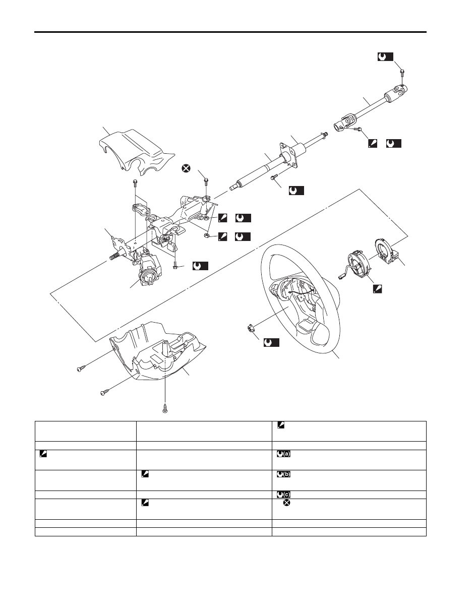
Steering Wheel and Column Construction
S6JB0B6201001
This double tube type steering column has the following three important features in addition to the steering function:
• The column is energy absorbing, designed to compress in a front-end collision.
• The ignition switch and lock are mounted conveniently on this column.
• With the column mounted lock, the ignition and steering operations can be locked to inhibit theft of the vehicle.
To insure the energy absorbing action, it is important that only the specified screws, bolts and nuts be used as
designated, and that they are tightened to the specified torque. When the column assembly (6) is removed from the
vehicle, special care must be taken in handling it. Use of a steering wheel puller or a sharp blow on the end of the
steering shaft, leaning on the assembly, or dropping the assembly could shear the plastic shear pins which maintain
column length and position.
The driver air bag (inflator) module is one of the supplemental restraint (air bag) system components and is mounted
to the center of the steering wheel (1). During certain frontal crashes, the air bag system supplements the restraint of
the driver’s and passenger’s seat belts by deploying the air bags. The air bag (inflator) module should be handled with
care to prevent accidental deployment. When servicing, be sure to observe “Precautions on Service and Diagnosis of
Air Bag System in Section 8B”.
6B-2 Steering Wheel and Column:
16
10
(b)
17
(b)
9
8
4
6
7
15
(c)
14
(c)
12
(b)
2
(a)
5
1
11
(b)
13
18
3
I6JB0B620001-01
1. Steering wheel
9. Steering column lower seal
17. Steering lower shaft assembly upper joint bolt
: After tightening all mounting bolts and nuts and all
joint bolts and nuts, tighten lower shaft lower joint bolt.
2. Steering shaft nut
10. Steering lower shaft assembly
18. Steering angle sensor (ESP
® model)
3. Contact coil cable assembly
: Fit lower fitting part first and
then fit upper fitting part.
11. Steering column assembly mounting bolt
: 33 N
⋅m (3.3 kgf-m, 24.0 lb-ft)
4. Steering column upper cover
12. Steering column assembly mounting nut
: After tightening column mounting nut, tighten
column mounting bolt.
: 25 N
⋅m (2.5 kgf-m, 18.0 lb-ft)
5. Steering column lower cover
13. Steering upper shaft assembly upper joint bolt
: 23 N
⋅m (2.3 kgf-m, 17.0 lb-ft)
6. Steering column assembly
14. Steering upper shaft assembly upper joint nut
: After tightening upper shaft mounting bolts,
tighten upper shaft joint nut.
: Do not reuse.
7. Steering lock assembly
15. Steering upper shaft mounting bolt
8. Steering upper shaft assembly
16. Steering lower shaft assembly lower joint bolt
Steering Wheel and Column: 6B-3
Diagnostic Information and Procedures
Air Bag Steering Wheel and Column Symptom
Diagnosis
S6JB0B6204001
For diagnosis of the steering wheel and steering column,
refer to “Steering Symptom Diagnosis in Section 6A”.
For diagnosis of the air bag system, refer to “Air Bag
Diagnostic System Check in Section 8B”.
Air Bag Steering Wheel and Column Inspection
and Repair Required after Accident
S6JB0B6204002
After accident, whether the air bag has been deployed or
not, be sure to checks, inspections and repairs
described under “Checking Steering Column for
Accident Damage” as well as “Repair and Inspection
Required after Accident in Section 8B”.
Diagnosis and Servicing of Air Bag Steering
Wheel and Column
S6JB0B6204003
For diagnosis and servicing, refer to “Precautions on
Service and Diagnosis of Air Bag System in Section 8B”.
Repair Instructions
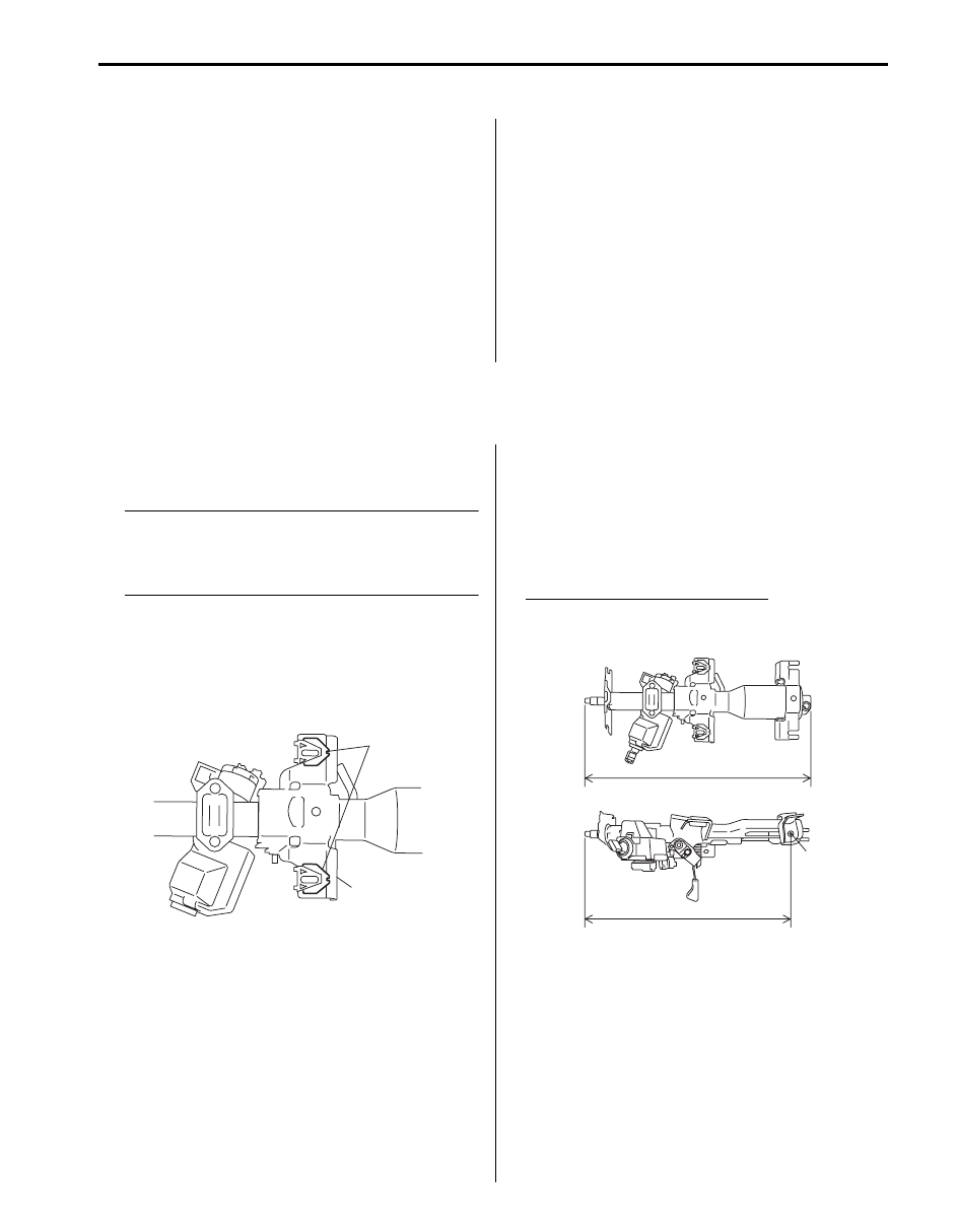
Checking Steering Column for Accident
Damage
S6JB0B6206001
NOTE
Vehicles involved in accidents resulting in
body damage, where steering column has
been impacted or air bag deployed, may have
a damaged or misaligned steering column.
• Check that 2 capsules (1) are attached to steering
column bracket (2) securely. Check clearance
between capsules and steering column bracket.
Clearance should be 0 mm (0 in.) on both sides. If
found loose or clearance, replace steering column
assembly.
• Check two rivets (1) of steering column assembly for
loose, crack and breakage. If found loose, crack and
breakage, replace steering column assembly with
new one.
• Take measurement “a” and “b” as shown in the figure.
If it is shorter than specified length, replace column
assembly with a new one.
Steering column assembly length
“a”: 471.0
± 1.0 mm (18.54 ± 0.04 in.)
“b”: 423.9
± 1.0 mm (16.69 ± 0.04 in.)
1
2
I5JB0A620002-01
“a”
“b”
1
I5JB0A620003-02
Нет комментариевНе стесняйтесь поделиться с нами вашим ценным мнением.
Текст