Suzuki Grand Vitara JB627. Manual — part 396
9F-12 Security and Locks:
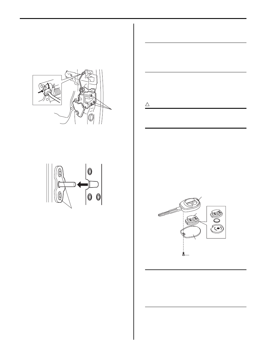
Installation
Reverse removal procedure to install rear end door lock
assembly noting the following instruction.
• Tighten rear end door latch bolt to specified torque.
Tightening torque
Rear end door latch bolt (a): 5 N·m (0.5 kgf-m, 4.0
lb-ft)
• Adjust door latch striker so that its center aligns with
the center of groove in door latch base.
Tightening torque
Rear end door striker screw (a): 24 N·m (2.4 kgf-
m, 17.5 lb-ft)
Rear End Door Lock Assembly Inspection
S6JB0B9606012
• Check that door opens and closes smoothly and
properly.
• Check that door stops in the secondary latched
position properly (preventing door from opening
freely) and that door closes completely in the fully
latched position.
• Adjust door latch striker position, if necessary.
Replacement of Transmitter Battery (Other than
Keyless Start Model)
S6JB0B9606013
NOTE
For keyless start model, perform
“Replacement of Remote Controller Battery
in Section 10E” instead of “Replacement of
Transmitter Battery (Other than Keyless Start
Model)”.
If transmitter becomes unreliable, replace transmitter
battery as follows.
1) Remove screw (1) and transmitter cover (2).
2) Remove transmitter (3) from transmitter holder (4).
CAUTION
!
Use care not to allow grease or dirt to be
attached on the printed circuit board and the
battery.
3) With tip of flat blade screwdriver put in slot of
transmitter, pry it open.
4) Replace the battery (lithium disc-type CR 1620 or
equivalent battery) so its (+) terminal faces “+” mark
on transmitter.
5) Fit together transmitter (3) and install it into
transmitter holder (4).
6) Install transmitter cover (2) and screw (1).
7) Make sure that door locks can be operated with
transmitter.
NOTE
• To prevent theft, be sure to break the
transmitter before discarding it.
• Dispose of the used battery properly
according to applicable rules or
regulations. Do not dispose of lithium
batteries with ordinary household trash.
(a)
I5JB0A960018-01
(a)
I5JB0A960019-01
2
3
4
1
I4RS0B960014-01
Security and Locks: 9F-13
Programming Transmitter Code for Keyless
Entry System (Other than Keyless Start Model)
S6JB0B9606014
NOTE
• Three transmitter codes can be registered.
• When a new transmitter code is registered,
the oldest one will be cleared.
• For keyless start model, perform
“Registration Procedure for Remote
Controller ID Code in Section 10E” instead
of “Programming Transmitter Code for
Keyless Entry System (Other than Keyless
Start Model)”.
If transmitter or BCM is replaced or additional
transmitter(s) is necessary, program transmitter code(s).
1) Confirm that all doors are closed and ignition key is
out of ignition key cylinder
2) Open driver side door.
3) Turn ignition switch to ON position, and then drawn
ignition key from ignition key cylinder within 10
seconds after that.
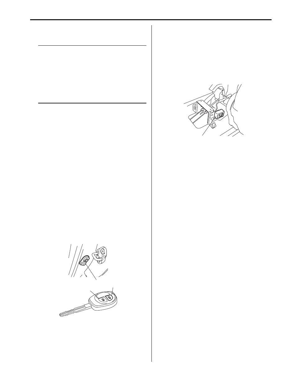
4) Push and release driver side door switch (1) at 3
times by hand within 20 seconds after removing
ignition key from ignition key cylinder.
5) Turn ignition switch to ON position, and then drawn
ignition key from ignition key cylinder within 10
seconds after that. All doors automatically lock and
unlock once.
With this, registration mode.
6) Push “UNLOCK” button (2) on transmitter (3) within
20 seconds after Step 5). All doors automatically lock
and unlock once.
With this, code registration is completed.
7) If an additional transmitter, needs to be programed
repeat the procedure of Step 1).
Keyless Entry Receiver Removal and
Installation
S6JB0B9606015
Removal
1) Disconnect negative cable at battery.
2) Remove console box from vehicle body referring to
“Console Box Components in Section 9H”.
3) Disconnect keyless entry receiver coupler.
4) Remove keyless entry receiver (1).
Installation
Reverse removal procedure.
1
3
2
I4RS0B960010-01
1
I5JB0A960020-01

9F-14 Security and Locks:
Keyless Entry Receiver and Its Circuit Inspection
S6JB0B9606016
1) Check that the voltage between the following terminals and body ground are specifications under each conditions.
If check result is not as specified, check applicable circuit for open or short. If circuit is normal, proceed to next
step.
Oscilloscope setting
CH1: 2V/DIV
CH2: 2V/DIV
TIME: 200 ms/DIV
1) Recheck keyless entry receiver as follows.
a) Substitute a known-good keyless entry receiver.
b) Record key code referring to “Programming Transmitter Code for Keyless Entry System (Other than Keyless
c) Recheck keyless entry receiver system.
1. Keyless entry receiver
2. Keyless entry receiver connector (view from harness side)
1
1
2
3
4
V
2
I5JB0A960021-01
Terminal
Circuit
Specification
Condition
L44-1
Power source
Figure [A]
Push “Lock” or “Unlock” button on transmitter.
0-1 V
Except the above-mentioned condition.
L44-3
Lock/Unlock output
signal circuit
Figure [A]
Push “Lock” or “Unlock” button on transmitter.
0-1 V
Except the above-mentioned condition.
L44-4
Ground
0-1 V
—
1. Lock/Unlock out put signal
2. Power source
I4RS0A960024-01
Security and Locks: 9F-15
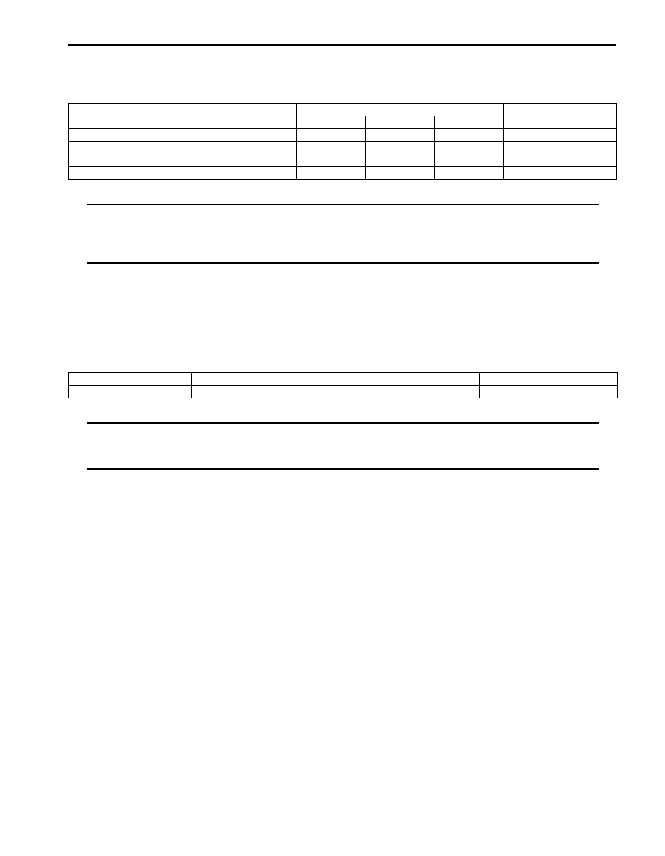
Specifications
Tightening Torque Specifications
S6JB0B9607001
NOTE
The specified tightening torque is also described in the following.
“Front Door Lock Assembly Components”
“Rear Door Lock Assembly Components”
“Rear End Door Lock Assembly Components”
Reference:
For the tightening torque of fastener not specified in this section, refer to “Fastener Information in Section 0A”.
Special Tools and Equipment
Recommended Service Material
S6JB0B9608001
NOTE
Required service material is also described in the following.
“Front Door Lock Assembly Components”
“Rear Door Lock Assembly Components”
Fastening part
Tightening torque
Note
N
⋅m
kgf-m
lb-ft
Door latch screw
5.0
0.5
4.0
Door latch striker screw
10
1.0
7.5
Rear end door latch bolt
5
0.5
4.0
Rear end door striker screw
24
2.4
17.5
Material
SUZUKI recommended product or Specification
Note
Grease
SUZUKI Super Grease A
P/No.: 99000–25011
Нет комментариевНе стесняйтесь поделиться с нами вашим ценным мнением.
Текст