Suzuki Grand Vitara JB627. Manual — part 397
9G-1 Seats:
Body, Cab and Accessories
Seats
Diagnostic Information and Procedures
Front Seat Heater Symptom Diagnosis (If Equipped)
S6JB0B9704001
Repair Instructions
Front Seat Components
S6JB0B9706001
Condition
Possible cause
Correction / Reference Item
Both seat back and
cushion do not become
hot although seat heater
switch is ON position
Wiring or grounding faulty
Repair.
“IG2 SIG” fuse blown
Replace fuse to check for short.
Seat heater switch faulty
Replace switch.
Seat heater circuit in seat back and/or
seat cushion faulty
Replace heater front back and/or heater front
cushion.
Only seat back does not
become hot although seat
heater switch is ON
position
Wiring faulty
Repair.
Seat heater circuit in seat back and/or
seat cushion faulty
Replace heater front back and/or heater front
cushion.
Only seat cushion does
not become hot although
seat heater switch is ON
position
Wiring faulty
Repair.
Seat heater circuit in seat cushion
Replace heater front cushion.
A
A
A
3
2
4
4
1
9
5
11
5
12
4
4
10
8
7
6
(a)
(b)
(b)
I6JB01970002-01
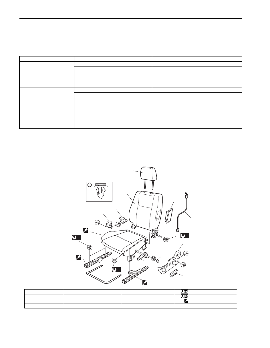
1. Seat cushion
5. Seat adjuster
9. Seat mounting bolt
: 23 N
⋅m (2.3 kgf-m, 17.0 lb-ft)
2. Seat back
6. Knob
10. Seat back bolt
: 35 N
⋅m (3.5 kgf-m, 25.5 lb-ft)
3. Headrestraint
7. Side air bag module (if equipped)
11. Seat cushion nut
: Non-disassemble (RH seat)
4. Cover
8. Side air bag harness (if equipped)
12. Seat lifter lever (if equipped)
Seats: 9G-2
Front Seat Removal and Installation
S6JB0B9706002
WARNING
!
Do not disassemble seat cushion and
adjuster of RH passenger seat since sensors
for occupant classification system are
equipped. Disassembling the seat cushion
and adjuster may cause improper air bag
deployment.
Removal
1) Disable air bag system referring to “Disabling Air
2) Disconnect seat harness coupler, seat heater
coupler and side air bag coupler, if equipped.
3) Remove 4 mounting bolts to remove seat assembly.
4) Disassemble and repair seat as necessary.
Installation
Reverse removal procedure to install front seat.
• Torque to specifications as shown in “Front Seat
• Enable air bag system referring to “Enabling Air Bag
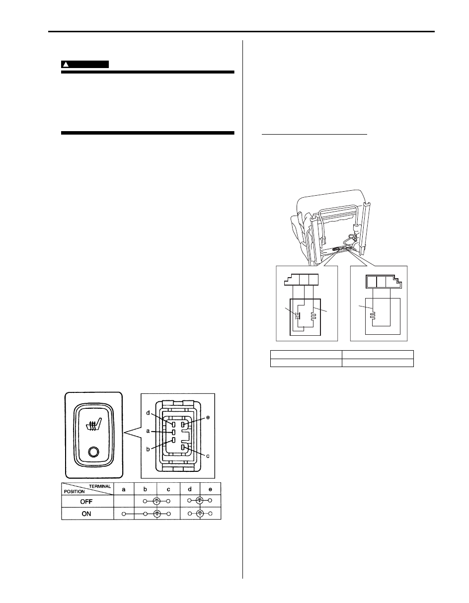
Front Seat Heater Switch (Driver and Passenger
Side) Inspection (If Equipped)
S6JB0B9706003
1) Confirm that ignition switch is OFF position.
2) Detach gear shift panel from front center console
box.
3) Disconnect seat heater switch coupler.
4) Check for continuity between terminals at each
switch position as shown below. If check result is not
as specified, replace.
Front Seat Heater Wire Inspection (If Equipped)
S6JB0B9706004
1) Confirm that seat heater switch is OFF position.
2) Disconnect coupler of seat heater under the seat
cushion.
3) Measure resistance between terminals as shown
below. If resistance is out of specification, replace
faulty seat cushion and/or seat back including seat
heater.
Seat heater circuit resistance
Seat cushion side [A] (between terminal “B” and
“C”, between terminal “A” and “C”): 4.7 – 5.7
Ω
(at 20
°C, 68 °F)
Seat back side [B] (between terminal “F” and
“D”: 10.7 – 13.1
Ω (at 20 °C, 68 °F)
I5JA01970001-01
1. Heater wire
[A]: Seat cushion side
2. Thermostat
[B]: Seat back side
A
B
C
D
E
F
[A]
[B]
1
1
2
I5JB0A970002-01
9G-3 Seats:
Rear Seat Components
S6JB0B9706005
Rear Seat Removal and Installation
S6JB0B9706006
Removal
1) Remove seat mounting bolt(s) in the bracket.
2) Fold rear seat back and unlock the seat cushion lock to pull forward the seat cushion.
3) Remove seat mounting nuts (bolts) to remove rear seat assembly.
4) Disassemble and repair seat as necessary.
Installation
Reverse removal procedure to install rear seat.
• Torque to specifications in “Rear Seat Components”.
Specifications
Tightening Torque Specifications
S6JB0B9707001
NOTE
The specified tightening torque is also described in the following.
“Front Seat Components”
“Rear Seat Components”
Reference:
For the tightening torque of fastener not specified in this section, refer to “Fastener Information in Section 0A”.
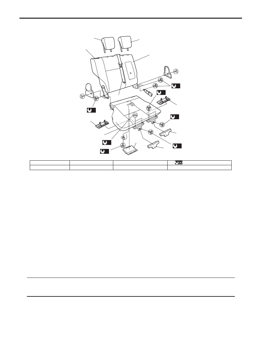
1. Seat cushion
3. Headrestraint
5. Rear center seat belt
: 45 N
⋅m (4.5 kgf-m, 32.5 lb-ft)
2. Seat back
4. Cover
6. Reclining lever
3
6
4
4
5
1
2
3
4
4
4
(a)
(a)
(a)
(a)
(a)
(a)
(a)
I6JB01970001-01
Interior Trim: 9H-1
Body, Cab and Accessories
Interior Trim
Repair Instructions
Floor Carpet Removal and Installation
S6JB0B9806001
Removal
1) Remove front seats and rear seats.
2) Remove seat belt lower anchor bolt.
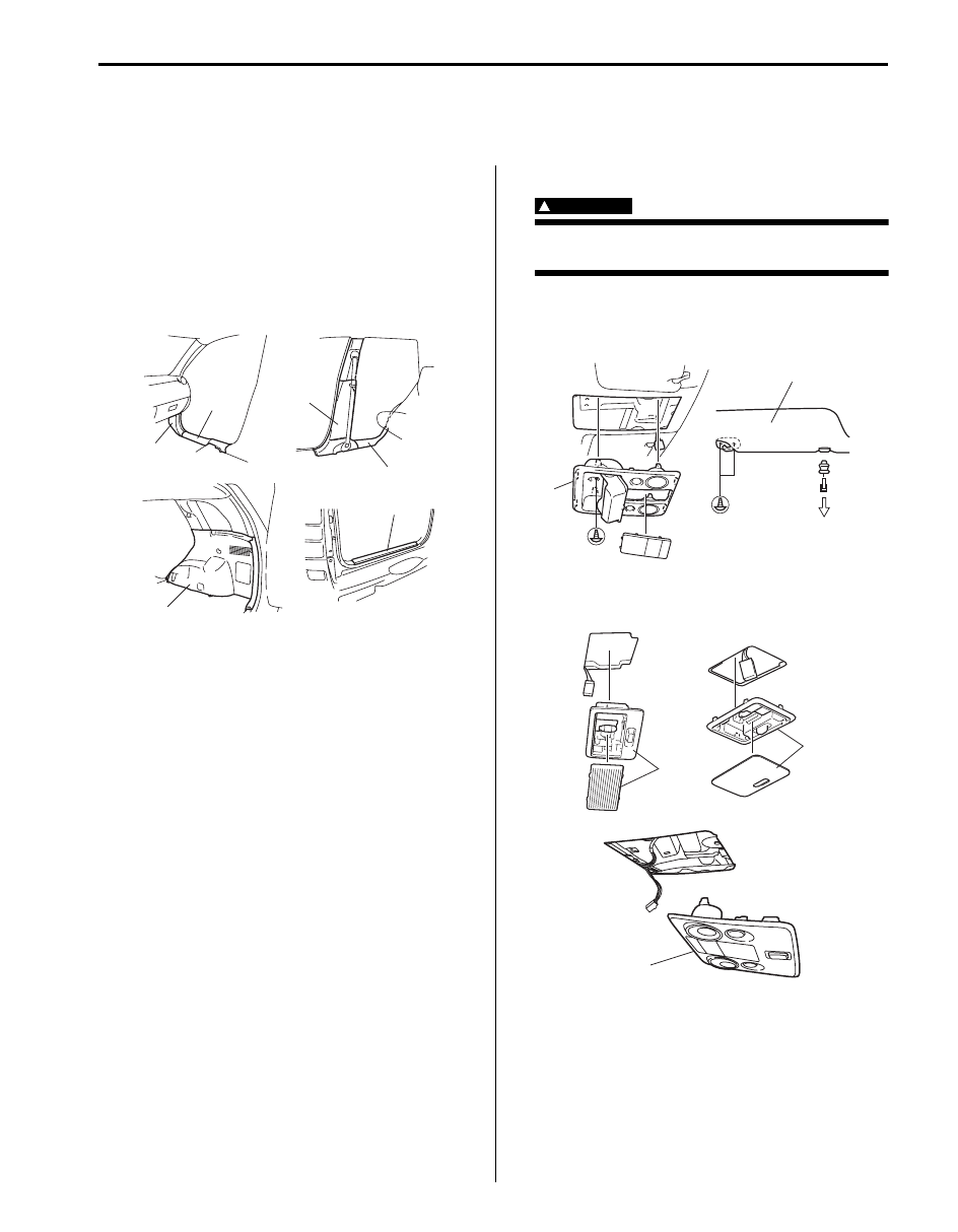
3) Remove front and rear side sill scuffs (1), front pillar
lower trims (2), center pillar inner lower trims (3),
back panel trim (4), rear quarter lower trims (5).
4) Remove front and rear console boxes.
5) Remove floor carpet.
Installation
Reverse removal sequence to install front floor carpet,
noting the following instruction.
• For tightening torque of rear seat mounting bolt and
nut, refer to “Rear Seat Components in Section 9G”.
• For tightening torque of front seat mounting bolt, refer
to “Front Seat Components in Section 9G”.
• For tightening torque of seat belt lower anchor bolt,
refer to “Front Seat Belt Components in Section 8A”
and “Rear Seat Belt Components in Section 8A”.
Head Lining Removal and Installation
S6JB0B9806002
WARNING
!
Refer to “Air Bag Warning: in Section 00”
before starting service work.
Removal
1) Remove overhead console (1) (if equipped) and
sunvisor (2).
2) Remove room light (2), luggage light (1) and spot
light (3) (if equipped).
1
2
1
3
4
5
I5JB0A980001-01
2
1
I5JB0A980002-02
2
1
3
I5JB0A980003-01
Нет комментариевНе стесняйтесь поделиться с нами вашим ценным мнением.
Текст