Suzuki Grand Vitara JB627. Manual — part 152
3C-12 Transfer:
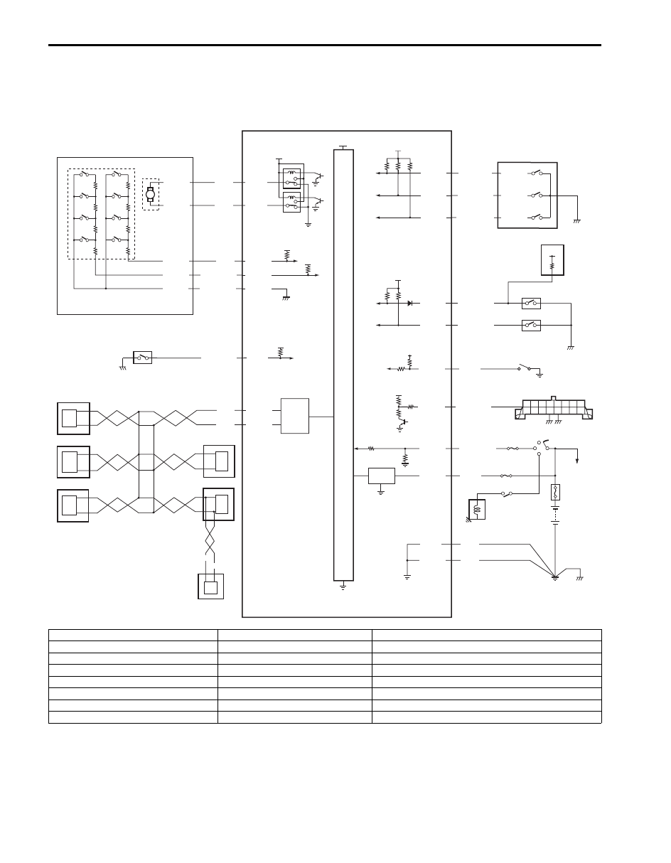
Schematic and Routing Diagram
4WD Control System Wiring Circuit Diagram
S6JB0B3302001
5V
5V
IG
5V
12V
E91-2
5V
12V
12V
+BB
YEL
RED/BLK
BLU
M
E91-3
E91-25
E91-26
RED
E91-24
BLK/YEL
E91-7
BLK/ORN
E91-21
PPL/WHT
E91-22
E91-23
RED
WHT
E91-18
E91-19
E91-20
E91-13
E91-14
E91-12
E91-11
E91-10
E91-1
BLK
BLK
WHT
BLK/WHT
RED/GRN
PNK/WHT
BLU/ORN
BLU/BLK
LT GRN
12V
12V
G59-2
G59-3
G59-4
C54-1
C54-4
C54-2
C54-3
C54-5
WHT/RED
WHT/BLU
1
2
3
4
5
6
7
8
9
10
12
11
13
14
15
17
18
19
20
21
23
22
16
E91-8
PNK
I5JB0A332007-03
1. Transfer actuator
9. ABS hydraulic unit / control module
17. DLC
2. Transfer actuator position switch
10. ECM
18. “IG COIL” fuse
3. Transfer actuator motor
11. 4WD control module
19. Ignition switch
4. CPP switch (for M/T model)
12. Transfer switch
20. “4WD” fuse
5. BCM
13. TCM (for A/T model)
21. Shift switch (for A/T model) or CPP switch (for M/T model)
6. TCM (for A/T model)
14. 4L/N switch
22. Main fuse box
7. Combination meter
15. Center differential lock switch
23. Starting motor
8. Keyless start control module (if equipped)
16. Diagnosis connector (if equipped)
Transfer: 3C-13
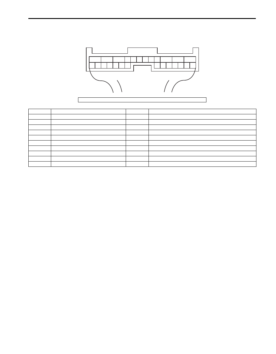
Terminal Arrangement of 4WD Control Module
1
2
3
4
5
6
7
8
9
10
11
12
13
14
15
16
17
18
19
20
21
22
23
24
25
26
[A]
I4JA01332038-01
[A]: Connector “E91” viewed from harness side
Terminal
Circuit
Terminal
Circuit
E91-1
Ground
E91-18
Transfer switch 1
E91-2
Transfer actuator motor 1
E91-19
Transfer switch 2
E91-3
Transfer actuator motor 2
E91-20
Transfer switch 3
E91-7
CPP switch
E91-21
Data link connector (DLC)
E91-8
Diagnosis connector
E91-22
CAN communication line (High)
E91-10
Ground
E91-23
CAN communication line (Low)
E91-11
Power source for internal memory
E91-24
Transfer actuator position switch (ground)
E91-12
Ignition switch
E91-25
Transfer actuator position switch 1 (power)
E91-13
4L/N switch
E91-26
Transfer actuator position switch 2 (power)
E91-14
Center differential lock switch
3C-14 Transfer:
Component Location
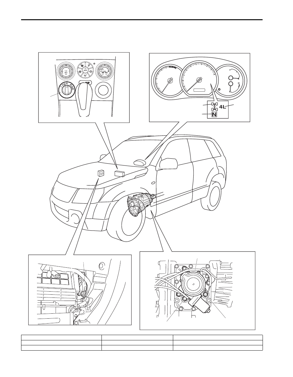
Transfer Shift Control System Components Location
S6JB0B3303001
6
7
5
1
8
2
3
4
I5JB0A332001-01
1. Transfer switch
4. N indicator
7. Center differential lock switch
2. Differential lock indicator
5. 4WD control module
8. 4L/N switch
3. 4L indicator
6. Transfer actuator

Transfer: 3C-15
Diagnostic Information and Procedures
4WD Control System Check
S6JB0B3304001
Refer to the following items for the details of each step.
Step
Action
Yes
No
1
Customer complaint analysis
1) Perform customer complaint analysis.
Was customer complaint analysis performed?
Go to Step 2.
Perform customer
complaint analysis.
2
DTC / freeze frame data check, record and clearance
1) Check for DTC.
Is there any DTC(s)?
Print DTC or write them
down and clear them by
referring to “DTC
Clearance”. Go to Step
3.
Go to Step 4.
3
Visual inspection
1) Perform visual inspection.
Is there any faulty condition?
Repair or replace
malfunction part. Go to
Step 11.
Go to Step 5.
4
Visual inspection
1) Perform visual inspection.
Is there any faulty condition?
Repair or replace
malfunction part. Go to
Step 11.
Go to Step 8.
5
Trouble symptom confirmation
1) Shift transfer to “4H”, “4H-lock”, “4L-lock” and “N”
positions referring to “4WD Control System Operation
Inspection”.
2) Confirm trouble symptom.
Is trouble symptom identified?
Go to Step 6.
Go to Step 7.
6
Rechecking and record of DTC / freeze frame data
1) Recheck for DTC referring to “DTC Check”.
Is there any DTC(s)?
Go to Step 9.
Go to Step 8.
7
Rechecking and record of DTC / freeze frame data
1) Recheck for DTC referring to “DTC Check”.
Is there any DTC(s)?
Go to Step 9.
Go to Step 10.
8
4WD control symptom diagnosis
1) Check and repair according to “4WD Control Symptom
Are check and repair complete?
Go to Step 11.
Check and repair
malfunction part(s). Go
to Step 11.
9
Troubleshooting for DTC
1) Check and repair according to applicable DTC flow.
Are check and repair complete?
Go to Step 11.
Check and repair
malfunction part(s). Go
to Step 11.
10 ) Check for intermittent problems
1) Check for intermittent problems.
Is there any faulty condition?
Repair or replace
malfunction part(s). Go
to Step 11.
Go to Step 11.
11 ) Final confirmation test
1) Clear DTC if any.
2) Perform final confirmation test.
Is there any problem symptom, DTC or abnormal condition?
Go to Step 6.
End.
Нет комментариевНе стесняйтесь поделиться с нами вашим ценным мнением.
Текст