Suzuki Grand Vitara JB627. Manual — part 273
7B-8 Air Conditioning System:
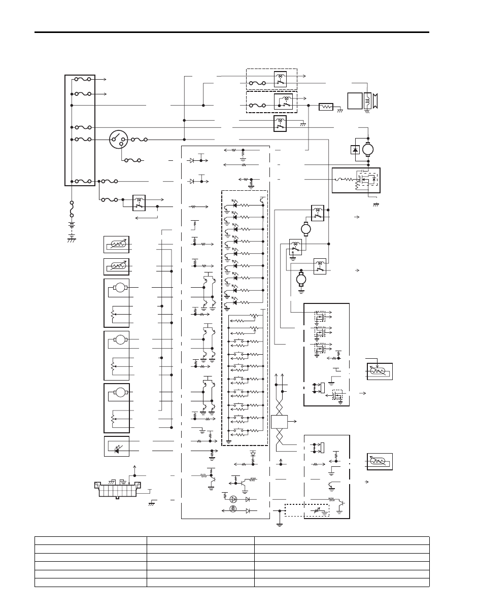
A/C System Wiring Circuit Diagram
S6JB0B7202001
12V
5V
M
12V
M
5V
5V
M
12V
12V
G52-1
G52-2
G52-8
G52-4
G52-15
G52-19
G52-20
12V
M
5V
5V
G52-21
G52-22
G52-23
G52-27
G52-28
G52-31
G52-32
G52-29
G52-30
G52-14
5V
5V
G52-18
G52-12
5V
12V
12V
5V
G52-13
G52-16
12V
5V
5V
12V
+BB
G52-17
G52-3
PPL/RED
WHT
RED/YEL
RED/WHT
WHT/BLK
BLU/BLK
BLK/RED
GRY
GRY/BLU
BLK/RED
WHT/RED
RED/WHT
ORN
GRN
RED/WHT
WHT/GRN
BLK/RED
GRY/RED
GRY/BLK
RED/WHT
WHT/BLU
BLK/RED
PNK
YEL
PPL/WHT
BLK
BLK/RED
RED/BLK
PPL/GRN
G52-10
G52-11
G52-6
G52-5
YEL/RED
PNK/GRN
PNK/BLK
RED/GRN
WHT/BLK
GRY/GRN
GRY/RED
GRY/BLK
M
M
RED/YEL
RED
RED/BLK
BLU/WHT
BLK
WHT/RED
BLK/RED
BLU/BLK
PNK
YEL/GRN
WHT/GRN
YEL/GRN
YEL/GRN
BLK/RED
BLU
BLU/WHT
BLU/BLK
RED
WHT
WHT/RED
WHT/BLU
BLK/RED
3
2
1
4
17
18
19
40
41
20
37
21
22
23
24
34
34
25
29
30
42
31
38
39
32
33
43
45
35
36
16
26
27
28
5
6
7
8
44
9
10
11
12
13
14
15
5V
47
46
WHT/GRN
48
49
I6JB01720003-01
1. Battery
18. Rear defogger relay
35. Theft deterrent light
2. Main fuse
19. Blower motor relay
36. Illumination light
3. Fuse box
20. Rear defogger
37. Indicator light, switch, selector
4. To radiator fan relay No.1
21. A/C compressor
38. To wheel speed sensor
5. To radiator fan relay No.3
22. Blower motor
39. To information display
6. Ignition switch
23. Blower motor selector
40. To ECM
Air Conditioning System: 7B-9
Component Location
A/C Control System Components Location
S6JB0B7203002
NOTE
The figure shows left-hand steering vehicle. For right-hand vehicle, parts with (*) are installed at the
opposite side.
7. Small light relay
24. Radiator fan relay No.1
41. To BCM
8. To BCM
25. Radiator fan No.1
42. To compressor relay
9. Evaporator temperature sensor
26. Radiator fan relay No.2
43. To rear defogger relay
10. Inside air temperature sensor
27. Radiator fan relay No.3
44. To combination switch
11. Temperature control actuator
28. Radiator fan No.2
45. AUTO-ON head light system vehicle
12. Air intake control actuator
29. ECM
46. Integration relay No.1
13. Air flow control actuator
30. Outside temperature sensor
47. Integration relay No.2
14. Sunload sensor
31. ABS or ESP
® control module
48. To other control module
15. Data link connector
32. BCM
49. To TCM, 4WD control module, combination meter, keyless start
control module and steering angle sensor.
16. HVAC control module
33. Refrigerant pressure sensor
17. Compressor relay
34. To fuse box

7B-10 Air Conditioning System:
1
*2
*7
*3
*6
*11
*10
9
8
4
5
25
12
24 26
14
22
23
16
15
21
13
17
19
18
20
I6JB0B720004-01
1. Outside temperature sensor
10. Blower motor
19. Theft deterrent light
2. Sunload sensor
11. Blower motor controller
20. Blower speed selector / Air intake selector
3. Inside temperature sensor
12. Temperature selector / A/C switch
21. Rear defogger switch
4. ECT sensor
13. “DEF” switch
22. “REC” indicator light
5. Refrigerant pressure sensor
14. “DEF / FOOT” switch
23. “FRE” indicator light
6. Evaporator temperature sensor
15. “FOOT” switch
24. MODE selector
7. Air intake control actuator
16. “BI-LEVEL” switch
25. HVAC control module (vehicle with A/C)
Air Conditioning System: 7B-11
Diagnostic Information and Procedures
Air Conditioning System Check
S6JB0B7204001
To ensure that system diagnosis is done accurately and smoothly, read “Precautions in Diagnosing Trouble” and follow
“Air Conditioning System Check”.
8. Temperature control actuator
17. “VENT” switch
26. “DEF” indicator light
9. Air flow control actuator
18. “AUTO” switch
Step
Action
Yes
No
1
Customer complaint analysis
1) Perform “Customer Complaint Analysis”.
Was customer complaint analysis performed according to
instruction?
Go to Step 2.
Perform customer
complaint analysis.
2
Visual inspection
1) Perform “Visual Inspection”.
Is there any faulty condition?
Repair or replace
malfunction part.
Go to Step 3.
3
DTC check
1) Perform “DTC Check”.
Is it malfunction code?
Go to Step 4.
Go to Step 5.
4
Troubleshooting for DTC
1) Check and repair according to DTC diag. flow.
Are check and repair completed?
Go to Step 7.
Check and repair
malfunction part(s).
5
Check for intermittent problem
1) Check for intermittent problem.
Is there faulty condition?
Repair or replace
malfunction part(s).
Go to Step 6.
6
Air conditioning system symptom diagnosis
1) Inspect and repair referring to “A/C System Symptom
Are inspect and repair complete?
Go to Step 7.
Inspect and repair
malfunction part(s).
7
Final confirmation test
1) Perform DTC check.
Is there any DTC?
Go to Step 4.
Air Conditioning system
is good condition.
Нет комментариевНе стесняйтесь поделиться с нами вашим ценным мнением.
Текст