Suzuki Grand Vitara JB627. Manual — part 272
7B-4 Air Conditioning System:
General Description
AUTO A/C System Description
S6JB0B7201001
The automatic air conditioning system (auto A/C), HVAC
control module automatically controls inside air
temperature, blower speed, airflow outlet and so forth.
Once users set up desired inside air temperature with
the temperature control selector, select “AUTO” position
of blower speed selector, push “AUTO” switch of mode
selector and push A/C switch, HVAC control module
detects inside air temperature, outside air temperature,
amount of sunlight, and engine coolant temperature by
means of inside air temperature sensor, outside air
temperature sensor, sunload sensor, and engine coolant
temperature (ECT) sensor respectively.
Then, HVAC control module keeps desired in-car
temperature at any time.
Then, HVAC control module keeps in-car temperature at
desired level.
HVAC Control System Description
S6JB0B7201002
For CAN communication system, refer to description on
“CAN Communication System Description in Section
1A”.
When following data are sent from control modules to
BCM through CAN communication, they are sent from
BCM to HVAC control module through serial
communication line.
• Engine coolant temperature
• Engine speed
• A/C refrigerant pressure
• Vehicle Speed (wheel speed)
• Outside air temperature
Based on above data, HVAC control module sends A/C
compressor ON / OFF request signal to BCM through
serial communication line.
BCM sends this signal through CAN communication to
ECM which then causes compressor relay to turn ON /
OFF.
For more information on signal transmission and
reception of Auto A/C system, refer to “Auto A/C
Electronic Control Input / Output Diagram”.
HVAC control module has a function to make initial
settings of temperature control actuator, air intake
actuator and air flow actuator.
Initial settings of actuators are automatically made when
engine is started for the first time after battery is
connected.
When initial settings are made, each actuator is forced to
operate for about 15 seconds continuously.
HVAC Control Module Operation Description
S6JB0B7201004
Temperature Control
HVAC control module calculates the target temperature
control door position based on signals from the
temperature selector, inside air temperature sensor,
outside air temperature sensor and sunload sensor and
controls the temperature control actuator so that the
current position of the temperature control door matches
its target position.
Fan Speed Control
HVAC control module calculates the target blower fan
speed based on signals from the temperature selector,
inside air temperature sensor, outside air temperature
sensor and sunload sensor, compares it with the current
blower fan speed inputted from the blower motor
controller to control the current blower fan speed to the
target level.
Air Flow Outlet Control
HVAC control module calculates the target temperature
control door position based on signals from the
temperature selector, inside air temperature sensor,
outside air temperature sensor and sunload sensor.
Using thus obtained target temperature control door
position, it further calculates the target air flow control
door position and controls the air flow control actuator so
that the current air flow control door position becomes
the target position.
Air Intake Position Control
HVAC control module determines the air intake position
based on signals from the temperature selector, inside
air temperature sensor, outside air temperature sensor
and sunload sensor and controls the air intake actuator.
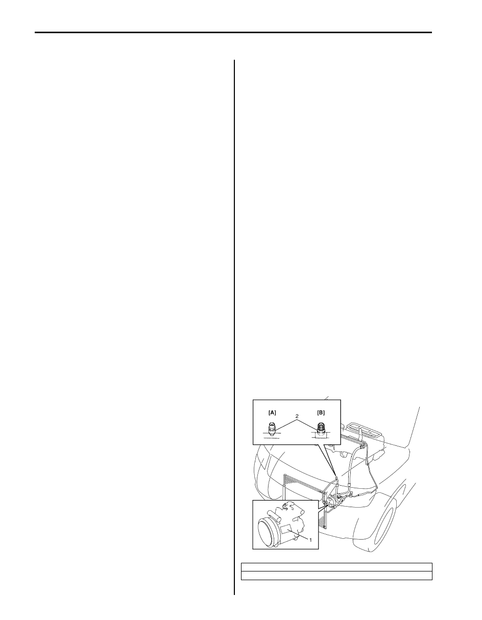
A/C Refrigerant Type Description
S6JB0B7201005
Whether the A/C in the vehicle being serviced uses
HFC-134a (R-134a) or CFC-12 (R-12) is indicated on
LABEL (1) on the compressor. Also, it can be checked
by the shape of the service (charge) valve (2).
[A]: HFC-134a (R-134a)
[B]: CFC-12 (R-12)
I5JB0A720005-01
Air Conditioning System: 7B-5
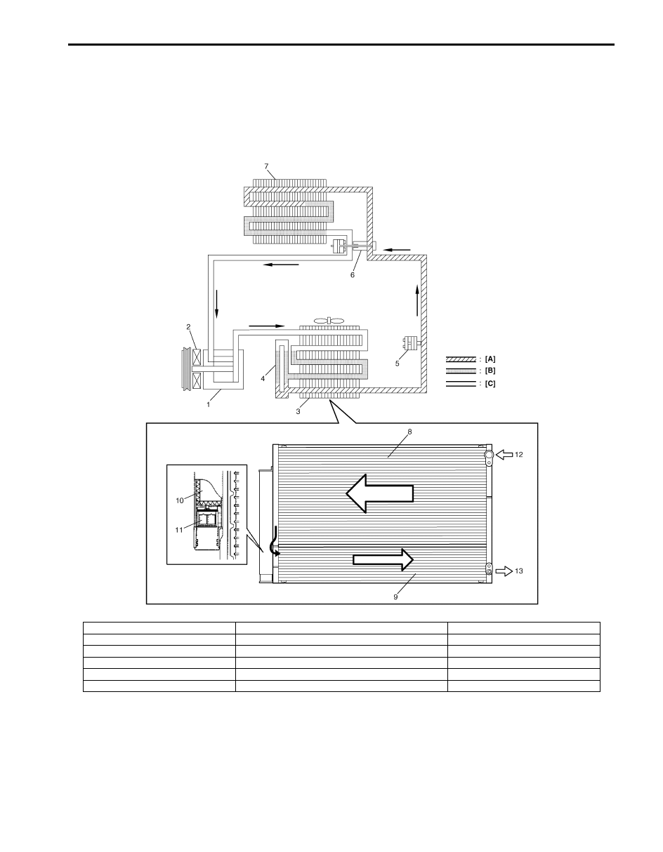
Sub-Cool A/C System Description
S6JB0B7201006
In the sub-cool A/C system (condenser (3) integrated with receiver / dryer (4)), the inside of the condenser is divided
into the condensation part and the sub-cooler part, and the receiver / dryer is located between those. In the receiver /
dryer (4), the refrigerant is separated into the vapor refrigerant and the liquid refrigerant. Only the liquid refrigerant is
delivered to the sub-cooler part of the condenser. The refrigerant is supercooled by the sub-cooler part of the
condenser.
I5JB0A720006-02
[A]: Liquid
4. Receiver / dryer
10. Desiccant
[B]: Vapor
5. Refrigerant pressure sensor
11. Filter
[C]: Superheated vapor
6. Expansion valve
12. Vapor refrigerant
1. Compressor
7. Evaporator
13. Liquid refrigerant
2. Magnet clutch
8. Condensation part
3. Condenser
9. Sub-cooler part
7B-6 Air Conditioning System:
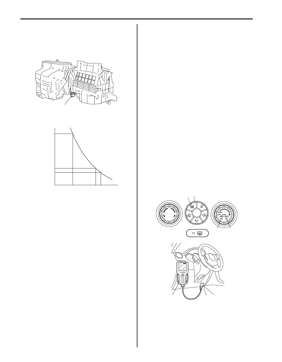
A/C Evaporator Temperature Sensor
Description
S6JB0B7201007
The A/C evaporator temperature sensor (1) is a
temperature sensor to sense the temperature of air
discharged from evaporator.
The electrical characteristic is shown.
When temperature is lower than specified, A/C controller
makes magnet clutch turn off to prevent evaporator from
frosting.
On-Board Diagnostic System Description
S6JB0B7201008
HVAC control module detects malfunction, which may
occur in the following area. When HVAC control module
detects any malfunction, the REC (recirculation)
indicator light (3) flashes on and off continuously after
turning ignition switch to ON position.
Abnormality exists (when air intake selector is operated
while “REC” indicator light is flashing), “FRE” indicator
light lights for 15 seconds and then “REC” indicator light
flashes.
• Outside temperature sensor
• Inside temperature sensor
• Sunload sensor (Short circuit)
• Wheel speed sensor
• CMP sensor
• CAN communication line
• Serial communication line
• A/C evaporator temperature sensor
• ECT sensor
• Temperature control actuator
• Air flow control actuator
• Air intake control actuator
• Temperature selector of HVAC control module
• Blower speed selector of HVAC control module
DTC can be checked by either one of the following ways.
• DTC can be checked by using SUZUKI scan tool (2)
connected to DLC (1).
• Without using SUZUKI scan tool, DTC can be
checked by reading the flashing pattern of both the
FRE (fresh air) indicator light (3) and the REC
(recirculation) indicator light (4).
• Current DTC and history DTC by pushing DEF
(defogger) switch (5) when DTC displayed by HVAC
control module.
• History DTC is such DTC which HVAC control module
saves in its memory when it detects current DTC for
60 seconds or more continuously.
• During indication of current DTC, DEF (defogger)
indicator light (6) is OFF. However DEF indicator light
(6) is ON during indication of history DTC.
1
I5JB0A720089-02
(k
Ω
)
11.4
3.9
3.3
0
32
25
77
30
86
(˚C)
(˚F)
Resistance
Temperature
I5JB0A720090-03
3
4
5
6
1
2
I5JB0A720093-03
Air Conditioning System: 7B-7
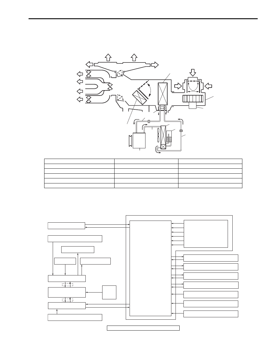
Schematic and Routing Diagram
Air Flow Diagram of A/C System
S6JB0B7202002
Auto A/C Electronic Control Input / Output Diagram
S6JB0B7202003
13
13
14
14
15
15
7
2
12
11
1
3
11
9
10
4
8
5
6
16
17
I5JB0A720008-02
1. HVAC unit
7. Expansion valve
13. Defroster air
2. Evaporator
8. Liquid pipe
14. Demister air
3. Blower fan motor
9. Suction pipe
15. Foot air
4. Compressor
10. Discharge pipe
16. Ventilation air
5. Condenser assembly
11. Recirculation air
17. Heater core
6. Receiver / dryer
12. Fresh air
Sunload sensor
Outside air temperature sensor
Evaporator temperature sensor
A/C refrigerant pressure sensor
Temperature selector
MODE (air flow) selector
Blower speed selector
Air intake selector
AUTO switch
A/C switch
Compressor relay
Blower motor controller
Temperature control actuator
Air flow control actuator
Air intake control actuator
BCM
ECM
Data link connector
HVAC control module
CPU
ECT sensor
Inside air temperature sensor
ABS control module or
ESP® control module
Wheel
speed
sensor
Radiator fan relay
*
*
I6JB01720002-03
*: CAN communication
Нет комментариевНе стесняйтесь поделиться с нами вашим ценным мнением.
Текст