Suzuki Grand Vitara JB627. Manual — part 241

5A-148 Automatic Transmission/Transaxle:
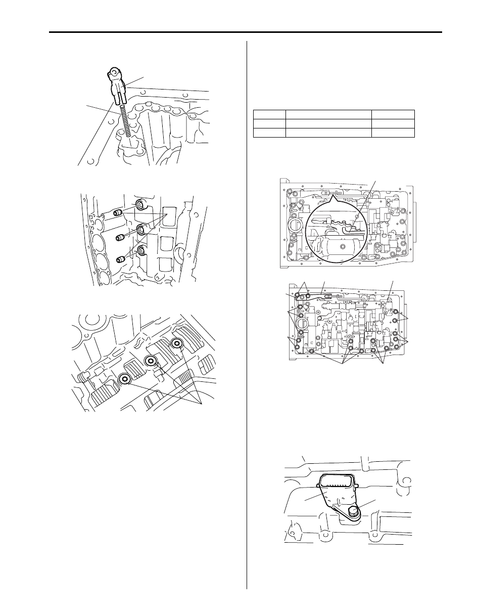
78) Connect parking lock rod (2) to manual shift lever (1)
as shown in the figure.
79) Install parking lock pawl bracket (1).
Tighten parking pawl bracket bolts (2) to specified
torque.
Tightening torque
Parking pawl bracket bolt (a): 7.4 N·m (0.74 kgf-
m, 5.5 lb-ft)
80) Turn manual shift lever (1) to “P” position, confirm
that rear planetary ring gear (2) is correctly locked up
by parking lock pawl (3).
81) After applying A/T fluid to new O-rings and then
install O-rings to accumulator pistons.
82) Install springs to transmission case.
Accumulator piston spring specification
1
2
I4JA01512270-01
1
2, (a)
I4JA01512271-01
1
2
3
I4JA01512272-01
Accumulator
spring
Free
length
Outside
diameter
Identification
painting
Forward
clutch
accumulat
or (1)
Inner
30.40 mm
(1.197 in.)
11.40 mm
(0.449 in.)
Pink
Outer
48.76 mm
(1.920 in.)
16.60 mm
(0.654 in.)
Green
Reverse
clutch
accumulat
or (2)
Inner
44.0 mm
(1.732 in.)
14.0 mm
(0.551 in.)
Yellow
Outer
73.35 mm
(2.888 in.)
19.90 mm
(0.784 in.)
Red
2nd (No.3) brake
accumulator (3)
64.5 mm
(2.540 in.)
19.5 mm
(0.768 in.)
Orange
Direct clutch
accumulator (4)
62.0 mm
(2.441 in.)
15.9 mm
(0.626 in.)
White
1
4
2
3
I4JA01512273-01
Automatic Transmission/Transaxle: 5A-149
83) Install spring (2) and check ball body (1) to
transmission case.
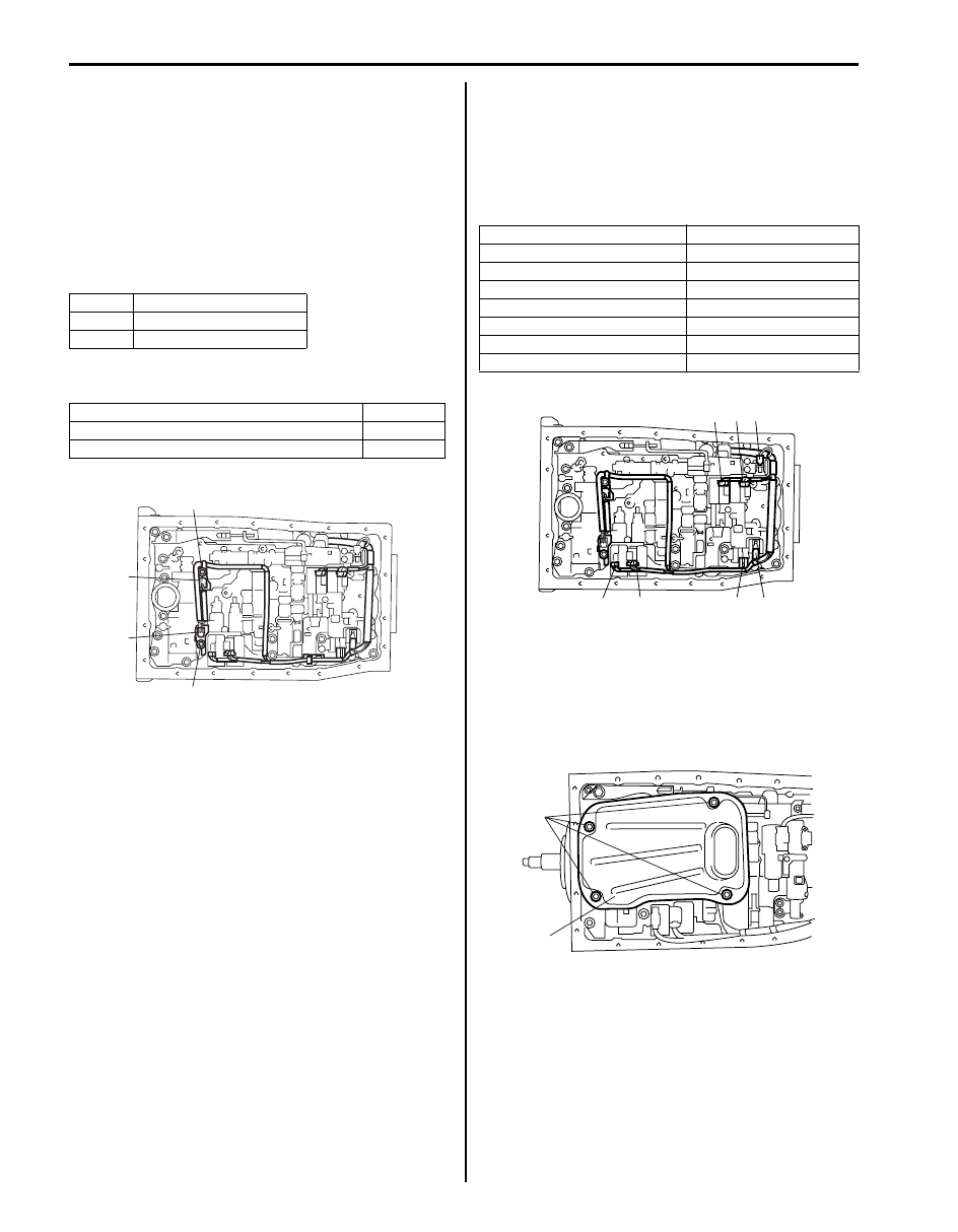
84) Install new brake drum gaskets (1).
85) Install new transmission case gaskets (1).
86) Align the groove of manual valve with pin of lever (1).
87) Install valve body assembly (2) by using bolts noting
their length shown below.
Tightening torque
Valve body bolt (a): 11 N·m (1.1 kgf-m, 8.0 lb-ft)
Valve body bolt length
88) Install spring plate (3) and manual shift lever spring
(4).
89) After applying A/T fluid to new O-ring and then install
transmission wire connector (2).
Tighten transmission wire connector bolt (1) to
specified torque.
Tightening torque
Transmission wire connector bolt (a): 5.5 N·m (
0.55 kgf-m, 4.0 lb-ft)
1
2
I4JA01512274-01
1
I4JA01512275-01
1
I4JA01512276-01
Bolt
Length
Pieces
A
25.0 mm (0.984 in.)
16
B
36.0 mm (1.417 in.)
3
1
A, (a)
3
2
B, (a)
4
A, (a)
A, (a)
A, (a)
A, (a)
A, (a)
I4JA01512277-01
2
1, (a)
I4JA01512278-01
5A-150 Automatic Transmission/Transaxle:
90) Install transmission fluid temperature sensor A (1)
and B (2) (if equipped).
91) Install clamp and bolts to specified torque.
Tightening torque
Transmission fluid temperature sensor clamp
bolt (a): 11 N·m (1.1 kgf-m, 8.0 lb-ft)
Transmission fluid temperature sensor clamp
bolt (b): 10 N·m (1.0 kgf-m, 7.0 lb-ft)
Transmission fluid temperature sensor clamp bolt
length
Transmission fluid temperature sensor harness
color
92) Connect pressure control solenoid-A connector (1),
pressure control solenoid-B connector (2), shift
solenoid-A connector (3), shift solenoid-B connector
(4), shift solenoid-E connector (5), TCC solenoid
connector (6) and pressure control solenoid-C
connector (7) to each solenoid valve.
Shift solenoid valve harness color
93) After applying A/T fluid to new O-ring and then install
O-ring to oil strainer.
94) Install oil strainer (1) to valve body assembly.
Tighten 4 oil strainer bolts to specified torque.
Tightening torque
Oil strainer bolt (a): 10 N·m (1.0 kgf-m, 7.0 lb-ft)
Bolt
Length
A
36.0 mm (1.417 in.)
B
12.0 mm (0.472 in.)
Fluid temperature sensor
Color
Transmission fluid temperature sensor A
Blue
Transmission fluid temperature sensor B
Orange
1
2
B, (b)
A, (a)
I6JB0B510011-01
Solenoid valve
Harness color
Pressure control solenoid-A
Green/Gray
Pressure control solenoid-B
Blue/Red
Pressure control solenoid-C
Purple/Yellow
Shift solenoid-A
White
Shift solenoid-B
Black
Shift solenoid-E
Light blue
TCC solenoid
Light green/Brown
1
2
3
4
5
6
7
I4JA01512280-01
1
(a)
I4JA01512281-01
Automatic Transmission/Transaxle: 5A-151
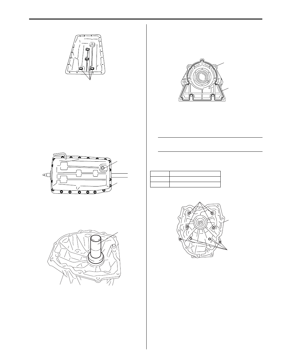
95) Install 4 transmission magnets (1).
96) Install a new gasket to oil pan.
97) Install oil pan to transmission case.
Tighten 20 oil pan bolts (1) to specified torque.
Tightening torque
Oil pan bolt (a): 4.5 N·m (0.45 kgf-m, 3.5 lb-ft)
98) Install drain plug (2).
Tighten drain plug to specified torque.
Tightening torque
Drain plug (b): 20 N·m (2.0 kgf-m, 14.5 lb-ft)
99) Install new oil seal (if removed) to transmission
adapter case by using special tool and hammer.
Special tool
(A): 09913–75520
100)Apply sealant continuously to transmission case
adapter sub assembly (1) mating surface as shown
in figure.
“A”: Sealant 99000–31230 (SUZUKI Bond
No.1216B)
101)Install transmission case adapter sub assembly (1)
to transmission case.
Tighten 8 transmission case adapter sub assembly
bolts to specified torque.
NOTE
Make sure to use new transmission case
adapter sub assembly bolts.
Tightening torque
Transmission case adapter sub assembly bolt
(a): 34 N·m (3.4 kgf-m, 24.5 lb-ft)
1
I4JA01512282-01
2, (b)
1, (a)
I4JA01512283-01
(A)
I4JA01512289-01
Bolt
Length
A
50.0 mm (1.969 in.)
B
40.0 mm (1.575 in.)
“A”
1
I4JA01512290-01
A, (a)
1
B, (a)
I4JA01512291-01
Нет комментариевНе стесняйтесь поделиться с нами вашим ценным мнением.
Текст