Suzuki Grand Vitara JB627. Manual — part 240
5A-144 Automatic Transmission/Transaxle:
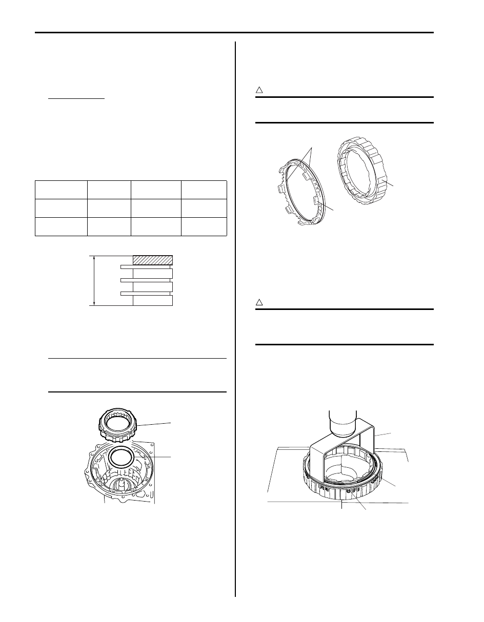
50) Using vernier calipers, measure the thickness
(length B) of the No.1 brake flanges, the No.1 brake
plates and the No.1 brake discs altogether at the
both end across a diameter, and calculate the
average.
Pack Clearance
0.42 – 0.72 mm (0.017 – 0.028 in.)
• Pack Clearance: Length A – Length B
Length B: 14.72 – 15.12 mm (0.58 – 0.595 in.)
51) If the pack clearance is out of specification, select
another flange with suitable thickness from the list
below and replace it.
Available No.1 brake flange thickness
52) Install one-way No.1 clutch assembly (1) and
planetary carrier thrust washer No.1 (2) to
transmission case.
NOTE
Make sure projection part of planetary carrier
thrust washer No.1 fit into holes of one-way
No.1 clutch inner race.
53) After applying A/T fluid to new 2 O-rings (1) and then
install O-rings to 2nd (No.3) brake piston (2).
54) Install 2nd (No.3) brake piston (2) to 2nd (No.3)
brake cylinder (3).
CAUTION
!
Do not twist or deviate O-ring during
installation.
55) Place 2nd (No.3) brake piston return spring (1) on
2nd (No.3) brake piston.
56) Compress 2nd (No.3) brake piston return spring (1)
until the 2nd (No.3) brake piston return spring is
lowered to the place 1 – 2 mm (0.039 – 0.078 in.)
from the snap ring groove by using special tool.
CAUTION
!
Be careful when applying pressure, for
overpressure will cause plate section of 2nd
(No.3) brake return spring to deform.
Special tool
(A): 09927–66540
57) Place snap ring (2) on 2nd (No.3) brake piston return
spring retainer being sure not to align snap ring end
gap with spring retainer claw.
Identification
No.
Thickness
Identification
No.
Thickness
0
2.0 mm
(0.079 in.)
2
2.4 mm
(0.094 in.)
1
2.2 mm
(0.087 in.)
3
2.6 mm
(0.102 in.)
B
I4JA01512357-01
1
2
I4JA01512249-01
1
2
3
I4JA01512250-01
2
1
(A)
I4JA01512352-01
Automatic Transmission/Transaxle: 5A-145
58) Install 2nd (No.3) brake piston (1) including 2nd
(No.3) brake cylinder (2) to transmission case.
59) Install snap ring (1) by using special tool being sure
not to align snap ring end gap with cut portion of
transmission case.
Special tool
(A): 09900–06108
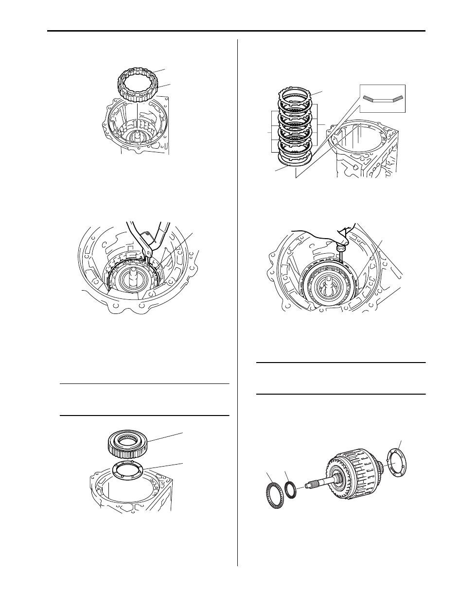
60) Fit clutch hub thrust washer (1) to one-way No.2
clutch assembly (2) with petroleum jelly so that
clutch hub thrust washer (1) does not fall off.
61) Install clutch hub thrust washer (1) and one-way
No.2 clutch assembly (2) to transmission case.
NOTE
Make sure projection part of clutch hub
thrust washer fit into holes of one-way No.2
clutch assembly.
62) Install 2nd (No.3) brake cushion plate (1), 2nd (No.3)
brake plates “P” and 2nd (No.3) brake discs “D”.
P - D - P - D - P - D - P - D
63) Install 2nd (No.3) brake flange “F”.
64) Install snap ring (1) by using flat end rod or the like
being sure not to align snap ring end gap with cut
portion of transmission case.
65) Fit clutch drum thrust washer No.2 (1) to clutch dram
and input shaft assembly with petroleum jelly so that
clutch drum thrust washer No.2 (1) does not fall off.
NOTE
Make sure projection part of clutch drum
thrust washer No.2 fit into holes of reverse
clutch hub.
66) Install thrust needle roller bearing No.1 (2) and thrust
needle roller bearing No.2 (3) to clutch dram and
input shaft assembly.
2
1
I4JA01512252-01
1
I4JA01512253-01
1
2
I4JA01512256-01
F
D
P
1
I4JA01512257-01
1
I4JA01512258-01
2
3
1
I6JB01510035-01
5A-146 Automatic Transmission/Transaxle:
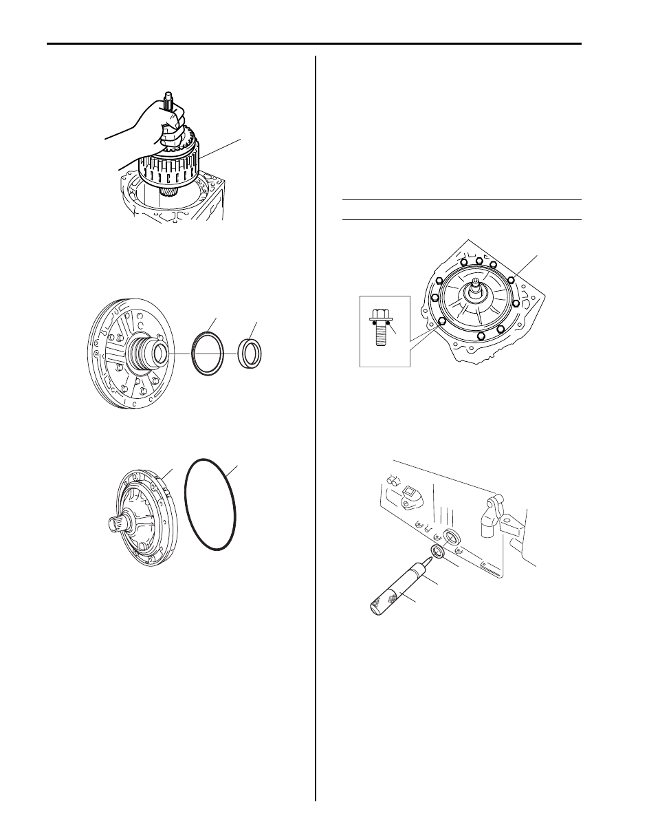
67) Install clutch dram and input shaft assembly (1) to
transmission case.
68) After applying petroleum jelly to thrust bearing race
No.1 (1) and thrust bearing race No.2 (2) so that
bearing race does not fall off, install it to oil pump
assembly.
69) After applying A/T fluid to new O-ring (1) and then
install O-ring to oil pump assembly (2).
70) Install oil pump assembly aligning bolt holes in
transmission case with oil pump assembly.
Apply seal packing to 10 oil pump bolts and tighten
them by certain amount of torque at each time one
after another till specified torque is attained.
Tightening torque
Oil pump bolt (a): 21 N·m (2.1 kgf-m, 15.0 lb-ft)
“A”: Sealant 99000–31230 (SUZUKI Bond
No.1216B)
NOTE
Make sure input shaft rotates smoothly.
71) Install new 2 manual shift shaft oil seals (1) to
transmission case by using special tools.
Special tool
(A): 09917–98221
(B): 09916–57330
1
I4JA01512260-01
2
1
I6JB01510034-01
2
1
I4JA01512262-01
“A”
(a)
I4JA01512263-01
1
(A)
(B)
I4JA01512264-01
Automatic Transmission/Transaxle: 5A-147
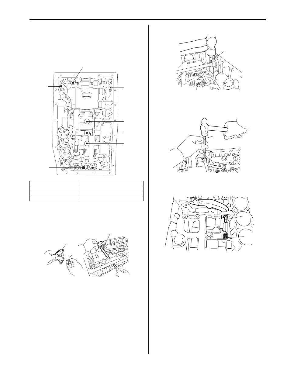
72) Apply compressed air (392 kPa, 4.0 kg/cm
2
, 57 psi)
into oil holes indicated in the figure. If there is no
noise, disassemble and check installation condition
of parts.
• When inspecting 1st & reverse (No.4) brake,
check oil hole (8) closed.
73) Install a new spacer (1) to manual shift lever (2).
74) Install manual shift shaft (3) to transmission case
through manual shift lever.
75) Drive in manual shift lever pin (1) by using hammer.
76) Align hole in sleeve cover with dent in manual shift
lever and caulk securely with pin punch (1). Then
check that manual shift shaft turns smoothly.
77) Install parking lock pawl (2), parking pawl pin (1) and
parking pawl spring (3).
1. Direct clutch
5. No.1 brake
2. Reverse clutch
6. No.2 brake
3. Forward clutch
7. 1st & reverse (No.4) brake
4. 2nd (No.3) brake
3
1
2
4
5
6
7
I6JB01510043-01
2
1
3
I4JA01512266-01
1
I4JA01512267-01
1
I4JA01512268-01
2
1
3
I4JA01512269-01
Нет комментариевНе стесняйтесь поделиться с нами вашим ценным мнением.
Текст