Suzuki Grand Vitara JB627. Manual — part 239
5A-140 Automatic Transmission/Transaxle:
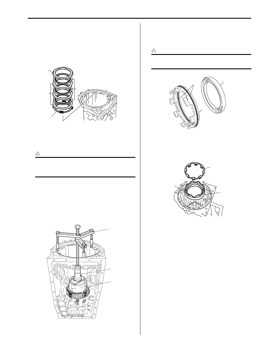
22) Install brake plate stopper spring (1) to transmission
case.
23) Install one-way No.3 clutch assembly (1) including
one-way No.3 clutch inner race (2) to transmission
case.
24) Install snap ring (1) by using special tool being sure
not to align snap ring end gap with cut portion of
transmission case.
Special tool
(A): 09900–06108
25) Install thrust bearing race No.4 (3) to middle
planetary gear assembly (1).
26) Install middle planetary gear assembly (1) including
planetary sun gear (2) into intermediate shaft.
27) After applying A/T fluid to new 2 O-rings (1) and then
install O-rings to No.2 brake piston (2).
28) Install No.2 brake piston (2) to No.2 brake cylinder
(3).
CAUTION
!
Do not twist or deviate O-ring during
installation.
29) Install No.2 brake cylinder (2) including No.2 brake
piston (1) to transmission case.
1
I4JA01512232-01
1
2
I4JA01512233-01
1
(A)
I4JA01512234-01
3
2
1
I4JA01512235-01
1
2
3
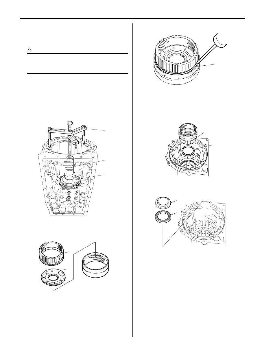
I4JA01512236-01
1
2
I4JA01512237-01
Automatic Transmission/Transaxle: 5A-141
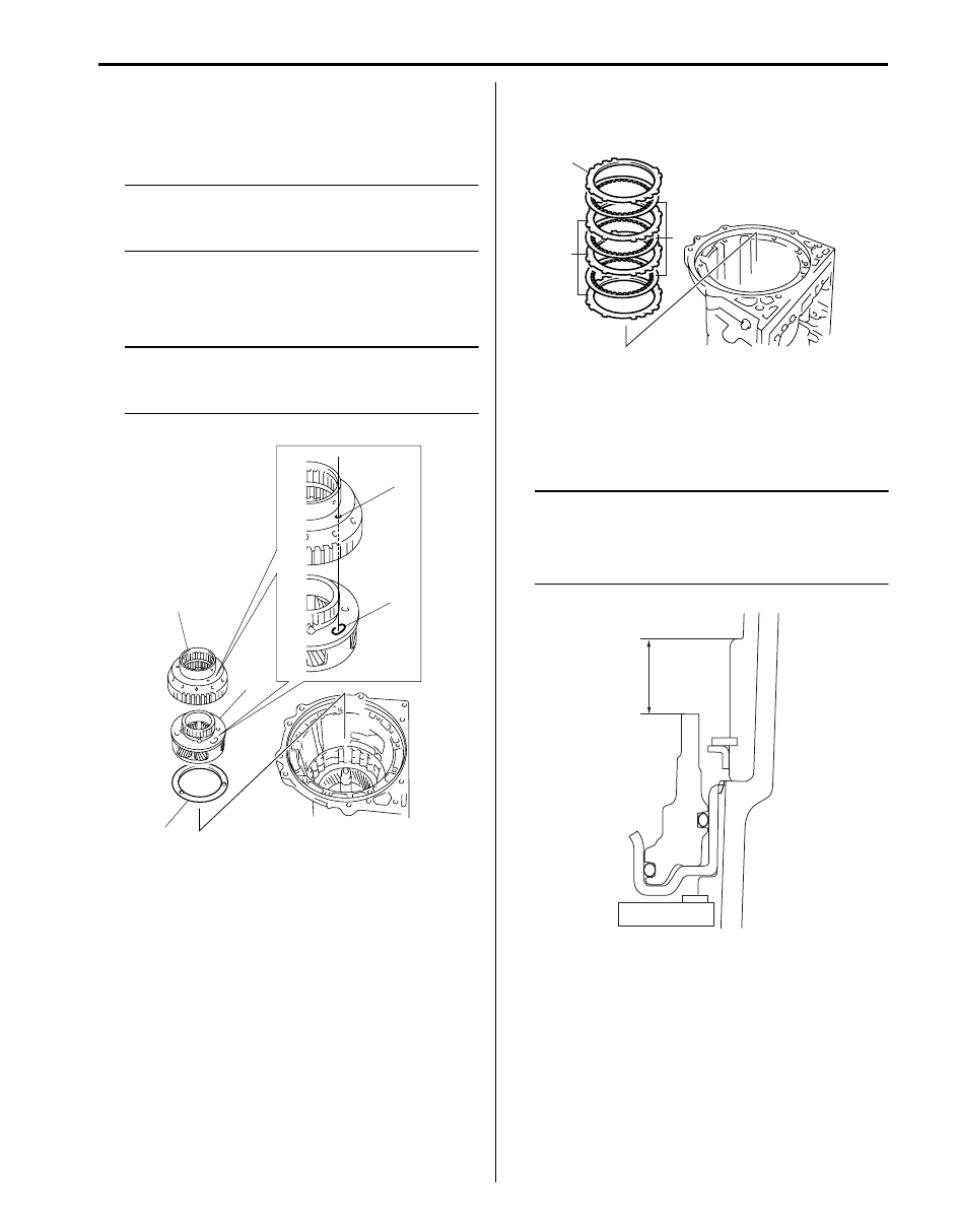
30) Install No.2 brake piston return spring (1) with spring
side of plate facing to No.2 brake disc side.
31) Install No.2 brake discs “D” and No.2 brake plates
“P” in the following order.
P - D - P - D - P - D
32) Install No.2 brake flange “F” with spring flange side
of flange facing to No.2 brake disc side.
33) Compress No.2 brake piston return spring until the
No.2 brake flange is lowered to the place 1 – 2 mm
(0.039 – 0.078 in.) from the snap ring groove by
using special tool.
CAUTION
!
Be careful when applying pressure, for
overpressure will cause No.2 brake return
spring to deform.
Special tool
(A): 09927–66510
(B): 09913–85210
(C): 09920–13120
34) Place snap ring on No.2 brake flange being sure not
to align snap ring end gap with cut portion
transmission case.
35) After applying A/T fluid to new 2 O-rings (1) and then
install O-rings to No.1 brake piston (2).
36) Install No.1 brake piston (2) to No.1 brake cylinder
(3).
CAUTION
!
Do not twist or deviate O-ring during
installation.
37) Install No.1 brake cylinder (2) including No.1 brake
piston (1) to transmission case.
38) Place No.1 brake piston return spring (3) on No.1
brake piston (1).
1
F
P
D
I4JA01512238-01
(A)
(B)
(C)
I4JA01512354-01
1
2
3
I4JA01512240-01
1
3
2
I4JA01512241-01
5A-142 Automatic Transmission/Transaxle:
39) Compress No.1 brake piston return spring until the
No.1 brake piston return spring is lowered to the
place 1 – 2 mm (0.039 – 0.078 in.) from the snap ring
groove by using special tool.
CAUTION
!
Be careful when applying pressure, for
overpressure will cause plate section of No.1
brake piston return spring to deform.
Special tool
(A): 09927–66530
(B): 09913–85210
(C): 09920–13120
40) Place snap ring on No.1 brake piston being sure not
to align snap ring end gap with cut portion
transmission case.
41) Install middle planetary ring gear (1) and front
planetary ring gear flange (2) onto front planetary
ring gear.
42) Install snap ring (1) by using flat end rod or the like.
43) After applying petroleum jelly to thrust needle roller
bearing (1) so that thrust needle roller bearing does
not fall off.
44) Install front planetary ring gear (2) and thrust needle
roller bearing (1) into intermediate shaft.
45) Install thrust needle roller bearing (1) and thrust
bearing race No.3 (2) onto front planetary ring gear.
(A)
(B)
(C)
I4JA01512355-01
2
1
I4JA01512243-01
1
I4JA01512244-01
2
1
I4JA01512245-01
2
1
I4JA01512246-01
Automatic Transmission/Transaxle: 5A-143
46) Fit planetary carrier thrust washer No.2 (1) to front
planetary gear assembly (2) with petroleum jelly so
that planetary carrier thrust washer No.2 (1) does not
fall off.
NOTE
Make sure projection part of planetary carrier
thrust washer No.2 fit into holes of front
planetary gear assembly.
47) Install front planetary gear assembly (2) and one-
way No.1 clutch inner race (3) onto front planetary
ring gear.
NOTE
Make sure align front planetary gear
assembly trenches (4) and one-way No.1
clutch inner race holes (5).
48) Install No.1 brake discs “D”, No.1 brake plates “P”
and No.1 brake flange “F” in the following order.
P - D - P - D - P - D - F
49) Using vernier calipers, measure the level difference
(length A) between the upper surface of the No.1
brake piston and the hitting surface of No.1 brake
flange at the both end across a diameter, and
calculate the average.
NOTE
• No.1 brake piston must be installed tightly
to the end face of transmission case.
• Length A:
15.29 – 15.77 mm (0.602 – 0.628 in.)
3
2
1
5
4
I4JA01512247-01
F
P
D
I4JA01512248-01
A
I4JA01512356-01
Нет комментариевНе стесняйтесь поделиться с нами вашим ценным мнением.
Текст