Suzuki Grand Vitara JB627. Manual — part 218

5A-56 Automatic Transmission/Transaxle:
DTC P0781: 1-2 Shift
S6JB0B5104031
DTC Detecting Condition and Trouble Area
Table for detecting condition
DTC Confirmation Procedure
WARNING
!
• When performing a road test, select a place where there is no traffic or possibility of a traffic
accident and be very careful during testing to avoid occurrence of an accident.
• Road test should be carried out with 2 persons, a driver and tester, on a level road.
1) Connect scan tool to DLC with ignition switch OFF.
2) Clear DTCs in TCM and ECM memories by using scan tool.
3) Start engine and warm it up to normal operating temperature.
4) Shift select lever to “N” and “D” range for each 10 seconds.
5) Start vehicle and increase vehicle speed to 65 km/h (40 mile/h) with throttle position 10% or more.
6) Stop vehicle.
7) Start vehicle and increase vehicle speed to 65 km/h (40 mile/h) with throttle position 10% or more.
8) Stop vehicle and turn ignition switch OFF.
9) Repeat Step 3) to 7) one time.
10) Stop vehicle.
11) Check DTC, pending DTC and freeze-frame data.
DTC Troubleshooting
DTC Detecting Condition
Trouble Area
DTC P0781:
When one of the following condition was detected while vehicle
running at 2 km/h (1.5 mile/h) or more in “D” range after engine
being warmed up.
• 1st gear ratio is detected although TCM command is for 2nd
gear and 4th gear is detected although TCM command is for
4th gear (See table below *1).
Or
• 1st gear ratio is detected although TCM command is for 2nd
gear and Neutral gear is detected although TCM command is
for 5th gear (See table below *2).
(2 driving cycle detection logic)
• Mechanical malfunction of 1-2 shift valve.
• Malfunction of valve body assembly.
• Mechanical malfunction of automatic
transmission (clutch, brake or gear etc.).
TCM output gear position
1st
2nd
3rd
4th
5th
Actual gear position
1-2 Shift (DTC P0781)
1st
1st*1, *2
3rd
4th*1
Neutral*2
Step
Action
Yes
No
1
Was “A/T System Check” performed?
Repair or replace
transmission valve body
assembly.
Go to “A/T System
Check”.
Automatic Transmission/Transaxle: 5A-57
DTC P0797: Pressure Control Solenoid “C” Stuck ON
S6JB0B5104032
DTC Detecting Condition and Trouble Area
Table for detecting condition
DTC Confirmation Procedure
WARNING
!
• When performing a road test, select a place where there is no traffic or possibility of a traffic
accident and be very careful during testing to avoid occurrence of an accident.
• Road test should be carried out with 2 persons, a driver and tester, on a level road.
1) Connect scan tool to DLC with ignition switch OFF.
2) Clear DTCs in TCM and ECM memories by using scan tool.
3) Start engine and warm it up to normal operating temperature.
4) Shift select lever to “N” and “D” range for each 10 seconds.
5) Start vehicle and increase vehicle speed to 65 km/h (40 mile/h) with throttle position 10% or more.
6) Stop vehicle and turn ignition switch OFF.
7) Repeat Step 3) to 5) one time.
8) Stop vehicle.
9) Check DTC, pending DTC and freeze-frame data.
DTC Troubleshooting
DTC Detecting Condition
Trouble Area
DTC P0797:
4th gear ratio is detected although TCM command is for 4th gear
and Neutral gear is detected although TCM command is for 5th
gear while vehicle running at 2 km/h (1.5 mile/h) or more in “D”
range after engine being warmed up.
(2 driving cycle detection logic)
• Mechanical malfunction of pressure control
solenoid valve-C.
• Malfunction of valve body assembly.
• Fluid passage clogged or leaking.
• Mechanical malfunction of automatic
transmission.
TCM output gear position
1st
2nd
3rd
4th
5th
Actual gear position
Stuck ON (DTC P0797)
1st
2nd
3rd
4th
Neutral
Step
Action
Yes
No
1
Was “A/T System Check” performed?
Go to Step 2.
Go to “A/T System
Check”.
2
Check pressure control solenoid valve-C for operation
referring to “Solenoid Valves (Shift Solenoid-A, Shift
Solenoid-B, Shift Solenoid-E, TCC Solenoid, Pressure
Control Solenoid-A, Pressure Control Solenoid-B, and
Pressure Control Solenoid-C) Inspection”.
Are they in good condition?
Clean fluid passage or
replace valve body
assembly.
Replace pressure
control solenoid valve-
C.
5A-58 Automatic Transmission/Transaxle:
DTC P0962 / P0966 / P0970: Pressure Control Solenoid “A” Control Circuit Low / Pressure Control
Solenoid “B” Control Circuit Low / Pressure Control Solenoid “C” Control Circuit Low
S6JB0B5104033
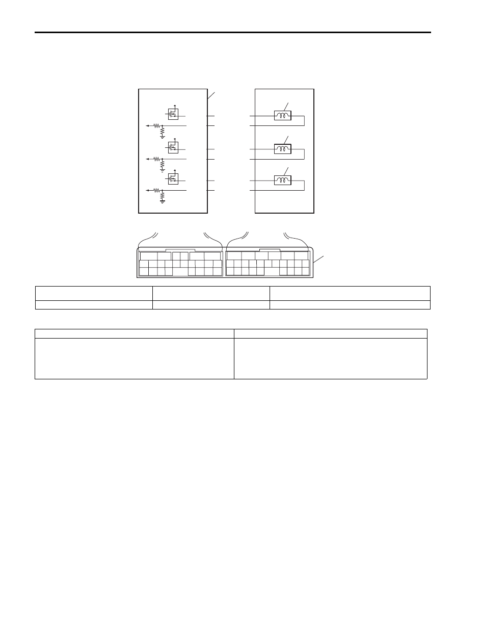
Wiring Diagram
DTC Detecting Condition and Trouble Area
DTC Confirmation Procedure
1) Connect scan tool to DLC with ignition switch OFF.
2) Clear DTCs in TCM and ECM memories by using scan tool.
3) Start engine.
4) Keep engine running at idle speed for 30 seconds or more.
5) Check DTC, pending DTC and freeze-frame data.
1
4
2
3
12V
12V
12V
E92-2
E92-4
E92-9
E92-22
E92-19
E92-21
YEL/RED
BRN/RED
LT GRN/BLK
LT GRN/RED
LT GRN
BRN/BLU
6
5
16 15 14 13 12 11
4 3
24 23
21
22
10 9
8
7
2
1
19
20
18 17
E92
17 16
26 25
15 14
6
5
3
4
2
13 12
23 22
24
11 10 9
21 20 19
8 7
18
1
E93
5
I6JB01510013-01
1. Pressure control solenoid valve-A
3. Pressure control solenoid valve-C
5. Terminal arrangement of TCM connector (viewed from
harness side)
2. Pressure control solenoid valve-B
4. TCM
DTC Detecting Condition
Trouble Area
Pressure control solenoid valve output voltage is too low
comparing with TCM command value.
(1 driving cycle detection logic)
• Pressure control solenoid valve circuit open or
shorted to ground.
• Malfunction of pressure control solenoid valve.
• TCM

Automatic Transmission/Transaxle: 5A-59
DTC Troubleshooting
Step
Action
Yes
No
1
Was “A/T System Check” performed?
Go to Step 2.
Go to “A/T System
Check”.
2
Check pressure control solenoid valve circuit for
ground short
1) Disconnect TCM connectors.
2) Check for proper connection to TCM at terminals “E92-
2” and “E92-4” (for pressure control solenoid valve-A),
“E92-9” and “E92-22” (for pressure control solenoid
valve-B) or “E92-19” and “E92-21” (for pressure control
solenoid valve-C).
3) If connection is OK, check continuity between terminal
“E92-2” (for pressure control solenoid valve-A), “E92-9”
(for pressure control solenoid valve-B) or “E92-19” (for
pressure control solenoid valve-C) of disconnected
harness side TCM connector and ground.
Is continuity indicated?
Pressure control
solenoid valve-A, -B or -
C control or ground
circuit is shorted to
ground circuit.
If circuit is OK, go to
Step 4.
Go to Step 3.
3
Check pressure control solenoid valve circuit for open
1) Check resistance between terminals “E92-2” and “E92-
4” (for pressure control solenoid valve-A), “E92-9” and
“E92-22” (for pressure control solenoid valve-B) or “E92-
19” and “E92-21” (for pressure control solenoid valve-C)
of disconnected harness side TCM connector.
Is it infinity?
Pressure control
solenoid valve-A, -B or -
C control or ground
circuit is open circuit.
If circuit is OK, go to
step 4.
Go to Step 4.
4
Inspection pressure control solenoid valve
Inspection pressure control solenoid valve referring to
“Solenoid Valves (Shift Solenoid-A, Shift Solenoid-B, Shift
Solenoid-E, TCC Solenoid, Pressure Control Solenoid-A,
Pressure Control Solenoid-B, and Pressure Control
Solenoid-C) Inspection”
Is check results satisfactory?
Intermittent trouble or
faulty TCM. Check for
intermittent trouble
referring “Intermittent
and Poor Connection
Inspection in Section
00”. If OK, substitute a
known-good TCM and
recheck.
Replace defective
pressure control
solenoid valve referring
“Solenoid Valves (Shift
Solenoid-A, Shift
Solenoid-B, Shift
Solenoid-E, TCC
Solenoid, Pressure
Control Solenoid-A,
Pressure Control
Solenoid-B, and
Pressure Control
Solenoid-C) Removal
and Installation”.
Нет комментариевНе стесняйтесь поделиться с нами вашим ценным мнением.
Текст